LMJ25 Current Sense Resistor
Products Specifications
- Package
- 2512 (6432 Metric)
- Features
- Current Sense, Industrial Grade, Large Electrode, Extremely Low Resistance Values, Very Low Inductance, Low Thermal EMF
- Series
- LMJ25
- Operating Temperature
- -55℃ ~ +170℃
- Temperature Coefficient
- 100ppm/℃
- Resistance
- 0.5 mOhms
- Power Rating
- 2W
- Tolerance
- 1%
- Mounting
- SMD / SMT
- Style
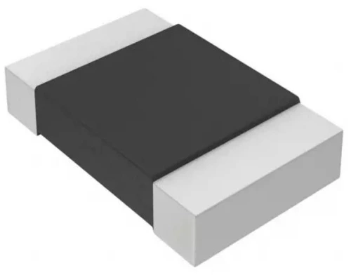
- Surface Mount Current Sensing Reistors
- Termination
- 2-Terminal
- Composition
- Metal Alloy
Description
- Proprietary processing technique produces extremely low resistance values
- Very low inductance
- Low thermal EMF
- Metallic Material
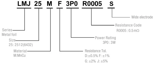
Part Numbering System
| Parameter | Standard |
|---|---|
| Power Rating | 2&3W |
| Resistance Value | 0.5mQ |
| Operating Temperature Range | -55 to +170℃ |
| Component Temperature Coefficient(TCR) | 100ppm/℃ |
| Maximum Working Voltage(V) | (PxR)1/2 |
Standard Electrical Specifications
| Type | Rating Power at 70℃ |
T.C.R. (ppm/℃) |
Resistance Range(mQ) D:0.5%;F:1.0% G:2.0%;J:5.0% |
Meterial | Electrode | Operating Temperature(℃) |
|---|---|---|---|---|---|---|
| LMJ25 | 2&3W | 100 | 0.5 | CuMn | Wide | -55~+170℃ |
Resistance Values of the 2512 Series, 2W Resistors
| Standard Resistance Values ( Ω ) | |||||||||
|---|---|---|---|---|---|---|---|---|---|
| 0ohm | 0.0005ohm | 0.001ohm | 0.002ohm | 0.003ohm | 0.004ohm | 0.005ohm | 0.006ohm | 0.008ohm | 0.01ohm |
| R000 | R0005 | R001 | R002 | R003 | R004 | R005 | R006 | R008 | R010 |
| Manufacturable Resistance Values ( Ω ) | ||||||||
|---|---|---|---|---|---|---|---|---|
| 0.00075ohm | 0.0012ohm | 0.0015ohm | 0.0025ohm | 0.0035ohm | 0.0038ohm | 0.0045ohm | 0.007ohm | 0.009ohm |
| R00075 | R0012 | R0015 | R0025 | R0035 | R0038 | R0045 | R007 | R009 |
Construction
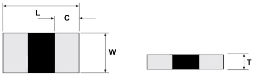
Unit: Millimeters
| Style | Resistance (mΩ) |
L | W | C | T | Material |
|---|---|---|---|---|---|---|
| LMJ25 | 0.5 | 6.4 ± 0.2 | 3.2 ± 0.2 | 2.5 ± 0.2 | 0.9 ± 0.2 | MnCu |
Recommended land pattern
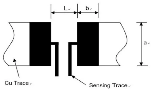
Unit: Millimeters
|
Resistance
Range (mΩ )
|
a | b | L |
|---|---|---|---|
| 0.5 |
4.0±0.1
|
3.1±0.1
|
1.3±0.1
|
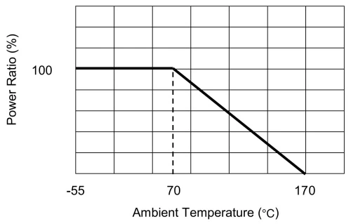
Power Derating Curve
For resistors operated in ambient temperatures 70℃, power rating shall be derated inaccording with the curve below:
Recommended Solder Curve
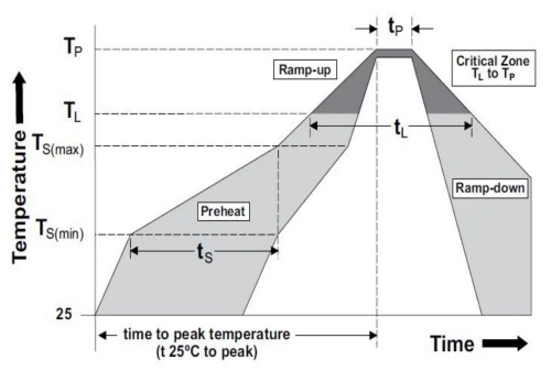 |
Reflow Condition | Pb-Free assembly | |
| Pre heat | - Temperature Min (Ts (min)) | 150℃ | |
| - Temperature Max (Ts (max)) | 200℃ | ||
| - Time (Min to Max) (ts) | 60-120 secs | ||
| Average ramp up rate (Liquidus Temp (TL) to peak) | 5℃ / second max | ||
| TS(max) to TL - Ramp-up Rate | 5℃ / second max | ||
| Reflow | - Temperature (TL)(Liquidus) | 217℃ | |
| - Temperature (tL) | 60 - 150 seconds | ||
| Peak Temperature (TP) | 260℃ | ||
| Time within 5℃ of actual peak Temperature (tp) | 20 - 40 seconds | ||
| Ramp-down Rate | 5℃ / second max | ||
| Time 25℃ to peak Temperature (TP) | 8 minutes Max | ||
| Wave Soldering | 260℃, 10 seconds max. | ||
| Hand Soldering | 350℃, 5 seconds max. | ||
Product Characteristics
| Item | Test condition / Methods | Limited | Standard | ||
|---|---|---|---|---|---|
| Resistance | Measuring resistance value at room temperature 25℃±5℃ | Refer to Spec | IEC60115-1 4.5 | ||
| Temperature coefficient of resistance |
TCR=(R-R0)/R0(T2-T1)X 10⁶ R0: resistance of room temperature R: resistance of 125℃ T1: Room temperature T2: Temperature at 125℃ |
Refer to Spec | MIL-STD-202 Method 304 |
||
| Short time Overload | Apply overload for 5 seconds and measure the resistance change rate after standing for 24 hours. 5 times the rated power for 5 seconds |
≤±0.5% | JIS-C5201-1 4.13 | ||
| Resistance to Soldering Heat |
260℃±5℃ time: 10sec± 1sec | ≤±0.5% | MIL-STD-202 Method 210 |
||
| Temperature Cycling | -55℃ (15min)/+150℃(15min), 1000 cycles | ≤±0.5% | JESD22 Method JA-104 |
||
| Low temperature Storage |
-55±2℃ for 96 hours,No power | ≤±0.5% | IEC 60115-1 4.23.4 | ||
| High Temperature Storage |
170℃ for 1000hours, No power | ≤±1% | MIL-STD-202 Method 108 |
||
| Bias Humidity | +85℃, 85%RH, 10%bias, 1000hours | ≤±0.5% | MIL-STD-202 Method103 |
||
| Solderability | 245±5℃, 3±1sec | The area of the electrode covered with fresh tin shall be greater than 95%. | JSTD-002 | ||
| Operational life | 70℃±2℃, 1000 hours, at rated power 1.5 hours “ON”, 0.5 hours “OFF” | ≤±1% | MIL-STD-202 Method 108 |
||
| Terminal bending | Solder the component onto a flex test board, mount the board on a flex testing machine, apply downward force at the center of the test board to achieve a 2 mm deflection, maintain the load for 60 seconds, and then measure the resistance change rage. |
≤±0.5% | JIS-C5201-1 4.33 | ||
Tapping & Package
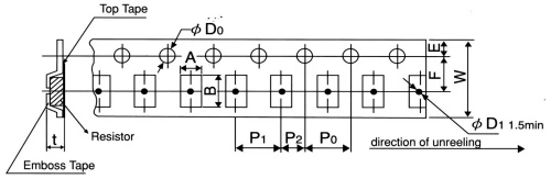
| Type | Pack | A ±0.2 |
B ±0.2 |
D0 +0.5 -0 |
E ±0.1 |
F ±0.05 |
P0 ±0.1 |
P1 ±0.1 |
P2 ±0.1 |
W ±0.2 |
D1 ±0.05 |
T ±0.15 |
|---|---|---|---|---|---|---|---|---|---|---|---|---|
| 2512 | Emboss | 3.60 | 6.90 | 1.50 | 1.75 | 5.50 | 4.00 | 4.00 | 2.00 | 12.00 | 1.50 | 1.20 |
Reel Specification
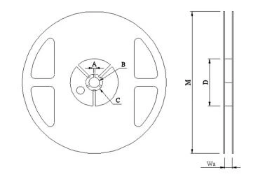
Unit: Millimeters
| Type | A | B | C | D | M | W |
|---|---|---|---|---|---|---|
| 2512 | 2.00±0.5 | 13.50±0.5 | 21.00±0.5 | 80.00±1.0 | 178.00±2.0 | 13.80±0.5 |
Packaging
Quantity: 4, 000pcs
8mm wide tape on 178mm(7 inch)
diameter reel -specification EIA Standard 481.
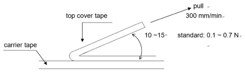
Peel Strength of Upper Belt
Stripping speed: 300 mm / min; The peel force is between 0.1N and 0.7n.
Storage Conditions & Shelf Life
It can be stored for 2 years under closed conditions with temperature of 5℃ ~ 35℃ and relative humidity of 40 ~ 75
Please avoid the following harsh environment during storage to avoid affecting the product performance and solder connectivity: the places with corrosive gases such as sea breeze, Cl2, H2S, NH3, SO2 and NO2 shall be stored without direct sunlight.
Precautions For Product Use
Avoid damaging the protective layer during manual welding or clamping with tweezers.
When the PCB is divided or fixed on the support, be careful to avoid excessive bending causing mechanical stress to the resistor.
It shall be used within the rated power range within the specification, especially when the power exceeds the rated value, which may affect the reliability of the product