Current Sense Resistors for SiC / GaN Inverter Systems
In modern power electronics, selecting suitable current sense resistors has become a critical part of SiC and GaN inverter design. The resistor must do more than provide a precise resistance value. It must also withstand high pulse current, control power loss, maintain low temperature drift, and preserve measurement stability within a compact power stage.
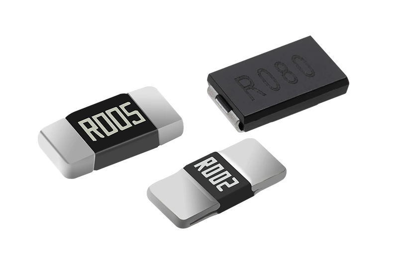
Standard current sense resistors may perform well in DC power supplies or lower-frequency converters, yet the same components may not provide predictable results in EV traction inverters, fast chargers, motor drives, and high-density industrial converters.
The question is no longer whether a resistor can measure current. The real question is whether its material, structure, terminals, thermal behavior, and production consistency match the inverter platform.
Why Standard Current Sense Resistors Are Not Suitable for SiC / GaN Systems
Many general-purpose current sense resistors were developed for stable DC loads or relatively moderate switching conditions. In those applications, engineers often select the component by checking resistance, tolerance, rated power, and package size.
SiC and GaN systems introduce a more demanding operating environment. Higher power density places greater current and heat into a smaller area. Fast load transitions create repetitive pulse stress, while compact mechanical layouts limit the copper area available for heat spreading.
| Selection Factor | Standard Power System | SiC / GaN Inverter System |
|---|---|---|
| Operating current | Stable or slowly changing | High continuous current with repeated transients |
| Power density | Moderate | High, with limited installation space |
| Resistor selection focus | Tolerance and rated power | Pulse capability, TCR, inductance, terminals, and thermal stability |
| Mechanical requirement | General PCB mounting | Low-stress, high-current connection structure |
| Validation requirement | Basic resistance and load testing | Pulse, temperature, cycling, and application-level testing |
A standard resistor can therefore meet its datasheet limits and still be unsuitable for a high-performance inverter. The problem is not necessarily component quality. The operating profile may simply be outside the conditions for which the product was optimized.
Applications requiring low resistance, high pulse-current capability, and strong mechanical construction frequently use metal alloy current sense resistors. Their conductive element and terminal structure make them suitable for many EV, power conversion, and industrial current measurement designs.
Performance Requirements for SiC / GaN Current Sense Resistors
A suitable resistor specification starts with the actual system limits. Engineers should define continuous current, short-duration surge current, target sense voltage, operating temperature, cooling conditions, PCB space, and required lifetime before comparing product series.
Five parameters usually determine whether a component can move from the prototype stage into reliable production.
Resistance Value and Usable Signal Level
The resistance value determines both the measurement signal and the power dissipated by the component.
Vsense = I × R
P = I²R
Assume an inverter needs to measure 200 A and the analog front end is designed around a 50 mV full-scale shunt signal:
R = 50 mV ÷ 200 A = 0.25 mΩ
At 200 A, the resistor dissipates:
P = 200² × 0.00025 = 10 W
A higher resistance would provide a larger signal, but it would also increase heat and conduction loss. A lower resistance would improve efficiency, yet it might reduce the signal below the useful input range of the amplifier and ADC.
This balance is why the best resistance value cannot be selected from a product catalog alone. It must be calculated from the measurement chain and the thermal budget together.
Continuous Power Is Only Part of the Rating
Rated power is usually specified under defined PCB, ambient, and heat-dissipation conditions. Real inverter assemblies rarely reproduce those conditions exactly.
A 3 W or 5 W component may be suitable for one PCB but overheat on another because copper thickness, pad dimensions, airflow, and nearby heat sources are different.
| Power Condition | Primary Design Concern | Required Verification |
|---|---|---|
| Continuous current | Steady resistor and terminal temperature | Thermal equilibrium test |
| Short pulse | Peak element energy | Single-pulse capability |
| Repeated pulse | Heat accumulation and fatigue | Pulse repetition testing |
| Fault surge | Element, solder, and terminal survival | Overload and destructive-limit evaluation |
Inverter projects should distinguish clearly between maximum continuous current and surge current. A resistor that survives a single startup pulse may still drift or develop solder fatigue after millions of repeated load cycles.
TCR and Long-Term Resistance Stability
Initial tolerance controls the resistance value at the reference temperature. TCR determines how that value changes as the resistor heats or cools.
For a 50 ppm/°C component subjected to a 100°C temperature change, the theoretical resistance shift is approximately 0.5%. A 25 ppm/°C part under the same change shifts by approximately 0.25%.
That difference can be significant when the inverter uses current feedback for torque control, protection, energy calculation, or diagnostic functions.
Long-term stability must also be checked separately. Load life, thermal cycling, terminal stress, and material aging may change resistance even after the component returns to room temperature.
Terminal Structure and Kelvin Measurement
Two-terminal components can be acceptable where current and accuracy requirements are moderate. High-current precision measurement usually benefits from a four-terminal or Kelvin-compatible structure.
The power terminals carry load current. The separate sense terminals measure the voltage directly across the resistance element without including most of the voltage drop from PCB copper, solder joints, or bus connections.
This improves repeatability across load and temperature conditions. It also makes the final system less dependent on assembly variation.
Pulse Capability and Mechanical Durability
Pulse performance depends on more than the resistor element. Terminal geometry, alloy thickness, weld or bond structure, solder joint area, and thermal expansion all influence product life.
A component may remain electrically functional after a high-current event but still suffer mechanical stress that appears later as resistance drift or an intermittent connection.
For compact assemblies where board height and current capacity must be balanced, slim metal alloy sampling resistors can be evaluated according to current rating, available PCB area, sensing requirements, and heat-spreading conditions.
Current Sense Resistor Selection Process for Inverter Projects
A structured selection process reduces the risk of choosing a component that passes early testing but fails during inverter integration.
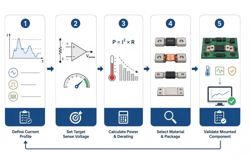
Step 1: Define the Real Current Profile
Start with the worst-case continuous current rather than the nominal operating value. Record startup current, braking current, short-circuit response, overload duration, and pulse repetition rate.
A useful current profile should include:
- maximum continuous RMS current
- peak current with pulse duration
- expected number of pulse cycles over service life
Without these values, the supplier cannot accurately assess element size, pulse margin, or terminal structure.
Step 2: Set the Target Sense Voltage
The target voltage should match the usable input range of the amplifier while leaving sufficient margin for tolerance, thermal drift, noise, and overload.
A high shunt voltage improves measurement resolution but increases heat. A very low shunt voltage reduces loss but demands a lower-offset, lower-noise analog front end.
Step 3: Calculate Power and Derating
Calculate continuous power using the maximum current and hot resistance, not only the nominal room-temperature value.
Then apply derating for ambient temperature, restricted airflow, enclosure temperature, and neighboring power devices. In compact SiC and GaN modules, nearby semiconductor and busbar temperatures can influence the resistor even when its own current remains unchanged.
Step 4: Select the Material and Package Structure
Material choice should match the most important requirement of the project. Some applications prioritize high current and overload capability. Others prioritize temperature stability or very tight precision.
| Resistor Technology | Main Strength | Typical Use |
|---|---|---|
| Metal alloy current sense resistor | Low resistance, compact package, strong pulse capability | EV inverters, converters, motor drives |
| Metal alloy shunt resistor | High-current structure and low-ohm measurement | Busbar, battery, charging, and industrial power systems |
| Slim metal alloy sampling resistor | Reduced profile for constrained PCB layouts | Compact power modules and control boards |
| Metal foil current detection resistor | Precision and stable resistance behavior | High-accuracy monitoring and calibration-sensitive circuits |
Step 5: Validate the Mounted Component
Datasheet evaluation should be followed by testing in the real PCB or busbar assembly. The mounted resistor behaves differently from a component tested on a standard evaluation board.
Validation should cover room temperature, maximum operating temperature, continuous load, repeated pulse current, startup, regenerative events, and expected fault conditions.
Measure both resistance stability and physical temperature. A stable case temperature does not always mean the internal element or terminal joint is operating within a safe margin.
Metal Alloy and Metal Foil Options for SiC / GaN Inverters
Metal Alloy Current Sense Resistors
Metal Alloy Shunt Resistors
Metal Foil Current Detection Resistors
Metal alloy and metal foil products can both be used in current measurement, but they are not interchangeable. Their strengths support different parts of the application spectrum.
Metal Alloy Current Sense Resistors
Metal alloy technology is widely used in low-ohm, high-current circuits. The conductive element can provide a direct current path with good pulse capability and a compact footprint.
This structure is suitable for EV traction inverters, onboard chargers, industrial motor drives, power supplies, and other systems where current capacity and thermal robustness are primary requirements.
Engineers should still compare resistance range, rated power, terminal type, TCR, dimensions, and recommended pad layout across individual series.
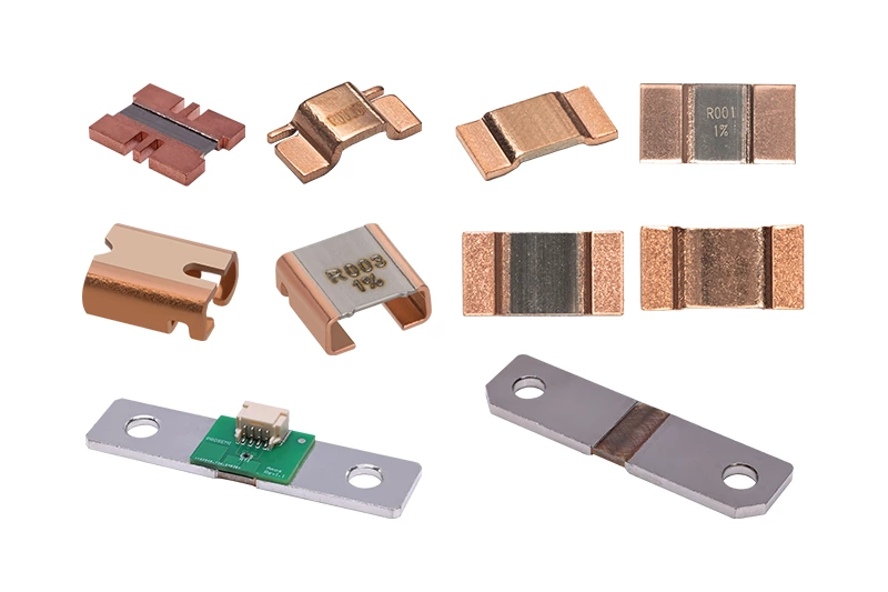
Metal Alloy Shunt Resistors
Metal alloy shunt resistors are suitable for applications requiring very low resistance and direct measurement of high current.
They may be used in DC links, battery circuits, charging systems, busbar assemblies, and high-power industrial equipment. Larger terminal structures can provide improved current distribution and mechanical strength compared with smaller chip-style components.
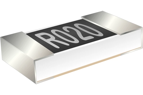
Metal Foil Current Detection Resistors
Metal foil current detection resistors may be considered where resistance precision, temperature behavior, or long-term calibration stability has a higher priority.
The final decision should be based on the entire application rather than assuming that one resistor technology is always superior.
Recommended Resistor Characteristics by Application
| Application | Primary Requirement | Suitable Product Direction |
|---|---|---|
| EV traction inverter | High current, pulse endurance, low loss | Metal alloy current sense or shunt resistor |
| GaN fast charger | Compact package, stable sensing, low parasitics | Slim metal alloy or precision alloy resistor |
| Onboard charger | Efficiency, thermal stability, production consistency | Metal alloy current sense resistor |
| Industrial motor drive | Overload capability and long operating life | Metal alloy shunt resistor |
| Precision power monitoring | Low drift and calibration stability | Metal foil current detection resistor |
This application matrix provides an initial direction, not a final part number. Current, voltage, pulse profile, cooling, mounting method, and required accuracy must still be confirmed before product approval.
Common Selection Mistakes
Selecting by tolerance alone. A 0.1% component is not automatically better if its pulse rating, package inductance, or thermal performance does not match the inverter.
Using nominal current instead of worst-case current. Continuous hill climbing, regenerative braking, startup, and fault response can expose the resistor to much higher stress than normal operation.
Comparing only rated power. Power ratings are tied to test conditions. Copper area, board thickness, airflow, and enclosure temperature can substantially change the usable power.
Ignoring terminal and mounting resistance. In very low-ohm systems, solder and copper resistance may become comparable to the resistor value unless the measurement points are correctly defined.
Skipping pulse-life verification. Surviving one overload event does not demonstrate reliability under repeated inverter load cycles.
Custom Current Sense Resistors for OEM Inverter Projects
Standard products can cover many power electronics designs, but inverter projects often require specific electrical or mechanical characteristics that are not available in a catalog part.
Typical OEM customization requests include resistance value, package dimensions, terminal geometry, rated current, TCR, tolerance, mounting method, and product marking.
| Customization Item | Engineering Benefit |
|---|---|
| Custom resistance value | Matches ADC signal range and power-loss target |
| Terminal geometry | Improves busbar or PCB integration |
| Package dimensions | Fits limited installation space |
| Material and TCR selection | Supports temperature and accuracy requirements |
| Pulse-current optimization | Improves overload and cycling reliability |
| Production marking and packaging | Supports traceability and assembly processes |
For an efficient technical review, OEM customers should provide the maximum continuous current, pulse waveform, allowable voltage drop, working temperature, mounting drawing, expected annual volume, and target validation requirements.
This information allows the manufacturer to evaluate whether an existing product is suitable or whether a custom low-ohm resistor design is required.
Conclusion
Current sense resistor selection for SiC and GaN inverter systems should focus on the operating profile of the complete power stage. Resistance tolerance remains important, but it is only one part of the decision.
Pulse-current capability, TCR, terminal construction, package dimensions, thermal behavior, long-term stability, and mounting conditions all influence whether the resistor will remain accurate and reliable throughout the inverter’s service life.
At Prosemi, we provide current sensing resistor solutions for EV traction inverters, charging systems, industrial motor drives, energy storage equipment, power supplies, and other high-current applications. Available product directions include metal alloy current sense resistors, metal alloy shunt resistors, slim sampling resistors, and metal foil current detection resistors.
Projects requiring a custom resistance value, package size, terminal structure, pulse-current rating, or application-specific product recommendation can be reviewed by our engineering team. Please contact Prosemi with your current profile, target sense voltage, temperature range, and installation requirements to discuss a suitable current sensing solution.
FAQ
What type of current sense resistor is suitable for a SiC inverter?
A suitable resistor normally combines low resistance, low TCR, strong pulse-current capability, stable terminals, and a package compatible with accurate Kelvin measurement. The exact product depends on current, target voltage, cooling, and installation space.
What resistance range is commonly used in inverter current sensing?
Many high-current applications use resistance values from fractions of a milliohm to several milliohms. The value should be calculated from maximum current, target sense voltage, and acceptable power loss.
Are standard SMD current sense resistors suitable for GaN converters?
They may be suitable for lower-current circuits, but high-power GaN converters often require better pulse performance, lower parasitics, and improved thermal behavior. Validation under real switching and load conditions is necessary.
Is a lower resistance value always better?
No. Lower resistance reduces heat and power loss, but it also reduces signal amplitude. The amplifier and ADC must still measure the resulting voltage accurately across the full operating range.
What is the difference between metal alloy and metal foil resistors?
Metal alloy resistors are commonly selected for low resistance and high-current capability. Metal foil products may provide advantages in precision, temperature behavior, or long-term resistance stability. Their suitability depends on the application.
Why is pulse-current capability important in inverter systems?
Inverters experience startup, braking, overload, and fault-related current pulses. The resistor must withstand both individual pulse energy and repeated thermal-mechanical stress over its service life.
Can Prosemi provide custom current sense resistors?
Custom options may include resistance value, dimensions, terminals, TCR, current capability, marking, and packaging. The feasibility depends on technical requirements and project volume.