PPTC Hold Current vs Trip Current: How Ihold and Itrip Really Work
When selecting a PPTC resettable fuse, two of the first parameters designers encounter are hold current (Ihold) and trip current (Itrip). These values appear simple, but they are often misunderstood.
For example, if a PPTC has an Ihold of 1 A and an Itrip of 2 A, what happens when the circuit draws 1.5 A? Does the device remain in its normal low-resistance state, begin heating, or eventually trip?
The answer is important because a PPTC does not behave like a digital switch with one precise current threshold. Its protection mechanism is strongly influenced by current, time, temperature, and thermal conditions.
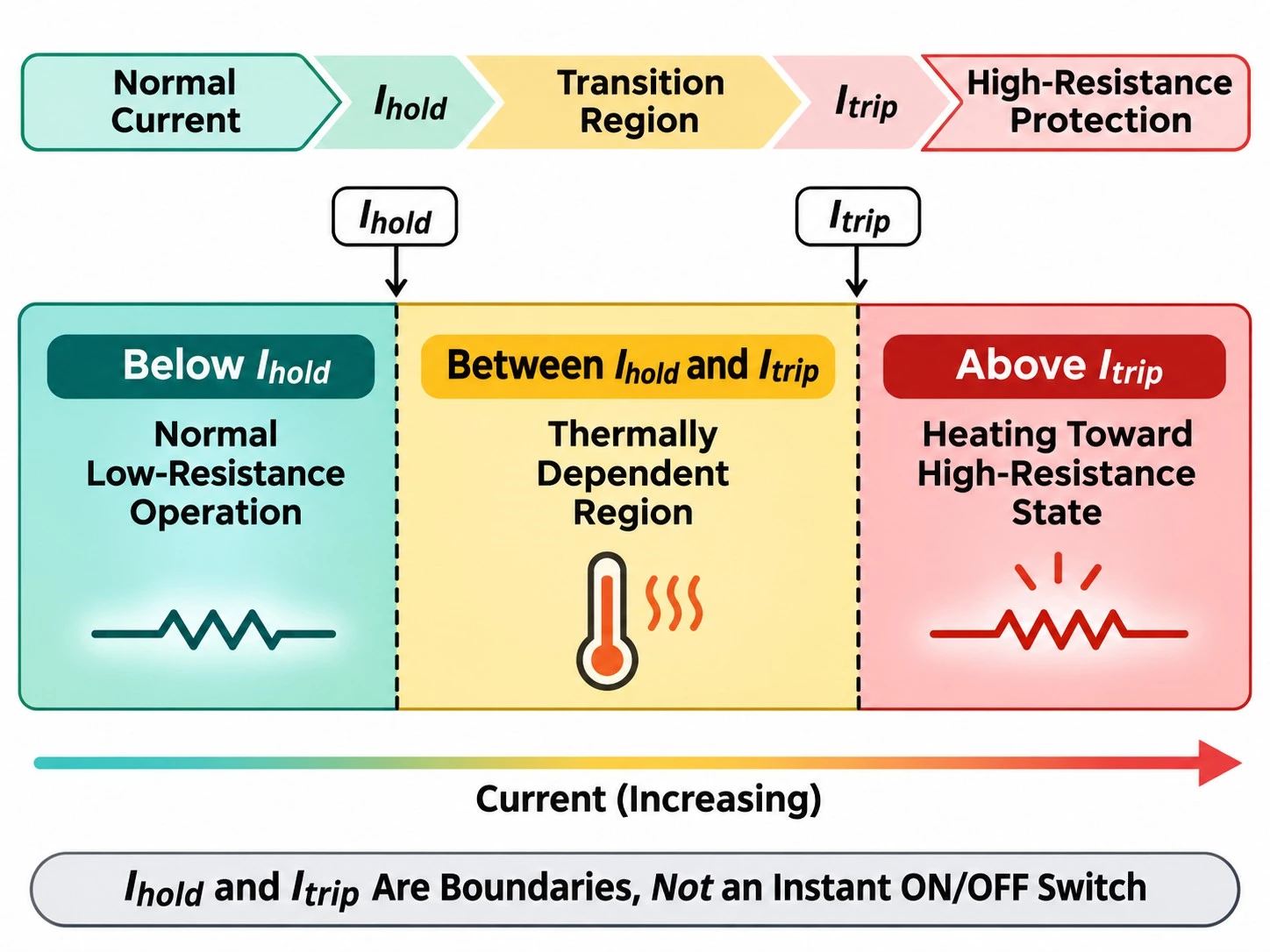
Ihold is not the exact trip point, and Itrip does not mean the device will open the circuit instantly.
To interpret a PPTC datasheet correctly, Ihold and Itrip should be evaluated together with time-to-trip, ambient-temperature derating, maximum voltage, and maximum fault current.
What Is PPTC Hold Current (Ihold)?
Hold current, usually written as Ihold or Ih, is the maximum current that a PPTC can carry continuously under specified conditions without transitioning into its high-resistance protective state.
In practical terms, Ihold describes the normal operating side of the device.
If a circuit normally draws 0.8 A, the selected PPTC must have enough hold-current capability to carry that current continuously under the actual operating temperature and thermal environment.
However, Ihold should not be treated as a universal current rating independent of conditions. PPTC behavior is temperature dependent, so a hold-current value specified at one ambient temperature may not represent the usable current at a much higher operating temperature.
For compact surface-mount applications, Prosemi's Low-R0 SMD Polymer PPTC Fuse range lists Ihold together with Itrip, Vmax, Imax, time-to-trip, Rmin and R1max, allowing the operating current to be evaluated alongside the device's protective behavior.
Ihold Defines the Normal Operating Boundary
Ihold is useful when determining whether the PPTC can remain in its low-resistance state during normal circuit operation.
A simplified design condition is:
Normal Operating Current < Usable Ihold at the Actual Ambient Temperature
The word usable is important. Designers should not simply match a 1 A load with a PPTC whose datasheet Ihold is exactly 1 A without checking temperature derating, production tolerance, startup current, and thermal margin.
What Is PPTC Trip Current (Itrip)?
Trip current, usually written as Itrip, describes a current condition associated with the transition from the normal low-resistance state toward the high-resistance protective state.
As excessive current flows through the PPTC, internal I²R heating increases the temperature of the polymer structure. Once sufficient heating occurs, the material changes state and its resistance rises sharply, limiting the fault current.
This is fundamentally different from a conventional one-time fuse, where the fusible element melts and physically interrupts the current path.
A tripped PPTC remains electrically connected and typically allows a reduced residual current to flow. It acts as a current-limiting high-resistance device rather than a perfect open circuit.
Itrip Does Not Mean Instantaneous Shutdown
One of the most common mistakes is to read Itrip as if it were an instantaneous switching threshold.
For example:
Itrip = 2 A
does not mean:
1.99 A = normal, 2.00 A = immediately disconnected.
The PPTC must absorb enough thermal energy to transition into its high-resistance state. The time required depends strongly on how far the actual current exceeds the normal operating range.
A severe fault can create rapid self-heating and a short trip time, while a smaller overload may take much longer to produce sufficient heating.
Ihold vs Itrip: What Is the Real Difference?
| Parameter | Ihold | Itrip |
|---|---|---|
| Main Meaning | Continuous current the PPTC can carry without tripping under specified conditions | Current associated with transition toward the high-resistance protective state |
| Main Design Role | Normal operation | Overcurrent protection |
| Device State | Low resistance | Heating toward or entering high resistance |
| Means Instant Trip? | No | No |
| Temperature Dependent? | Yes | Yes |
| Should Be Used Alone for Selection? | No | No |
A useful way to think about the two parameters is:
Ihold helps define where normal operation should remain stable.
Itrip helps define where protective behavior becomes dominant.
The region between them is where many misunderstandings begin.
What Happens Between Ihold and Itrip?
If the current is above Ihold but below Itrip, the PPTC should not be treated as being in a guaranteed, precisely defined digital state.
Its behavior depends on the balance between internally generated heat and the heat that can escape into the surrounding PCB, leads, enclosure, and ambient environment.
This means that a current between Ihold and Itrip may cause the device to warm gradually. Whether it remains stable, reaches thermal equilibrium, or eventually transitions into a high-resistance state depends on the actual operating conditions and the manufacturer's characteristic curves.
| Current Region | Typical Interpretation |
|---|---|
| Below Ihold | Normal low-resistance operation under specified conditions |
| Between Ihold and Itrip | Thermally dependent transition region; behavior must be checked against datasheet conditions |
| High Fault Current | Rapid self-heating drives the PPTC toward its high-resistance protective state |
This is why a circuit that must operate safely at a tightly defined maximum current should not rely only on the numerical gap between Ihold and Itrip.
If a load must operate normally at 5 A but must always be disconnected at 5.5 A, a PPTC may not provide the sharp current threshold expected from a precision electronic protection circuit.
Current Alone Does Not Determine the State
Several variables influence what happens in the transition region:
- current magnitude,
- duration of the overload,
- ambient temperature,
- PCB copper area and heat dissipation,
- device size and thermal mass,
- previous trip and thermal history.
The protection behavior should therefore be treated as a thermal process rather than a single current comparator.
Why Time-to-Trip Matters as Much as Itrip
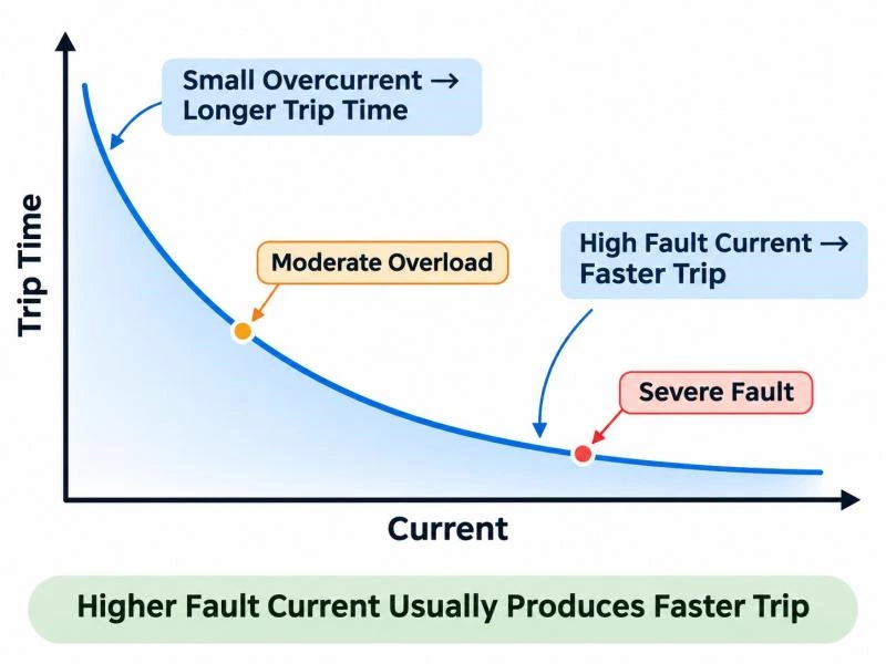
Time-to-trip tells the designer how long a PPTC requires to move from its low-resistance state into its high-resistance protective state under a specified overcurrent condition.
This parameter is essential because two faults with different current levels may produce very different protection times.
In general:
Higher Fault Current → Faster Self-Heating → Shorter Trip Time
while:
Lower Overcurrent → Slower Heating → Longer Trip Time
This current-versus-time behavior explains why Itrip should never be interpreted without looking at the time-to-trip data or trip curve.
A Datasheet Trip Point Is a Defined Test Condition
Manufacturers commonly specify time-to-trip at a particular test current.
For example, Prosemi's DIP PPTC model PG16-050 is listed with:
| Parameter | Value |
|---|---|
| Ihold | 0.5 A |
| Itrip | 1 A |
| Vmax | 16 V |
| Imax | 40 A |
| Time-to-Trip Test Current | 2.5 A |
| Time-to-Trip | 5 s |
The important point is that the 5-second trip specification applies to the stated 2.5 A test condition. It should not be interpreted as saying that the PPTC will trip in exactly 5 seconds whenever the current reaches Itrip.
Prosemi's DIP PPTC product table shows the same pattern across multiple parts: Ihold, Itrip and the time-to-trip test current are listed separately because they describe different aspects of the device.
Why Ambient Temperature Changes PPTC Behavior
PPTC protection is based on self-heating, so ambient temperature directly influences how much additional energy is required for the device to reach its high-resistance state.
At a higher ambient temperature, the PPTC starts closer to its transition region. Less additional self-heating may therefore be required to trigger protective behavior.
At a lower ambient temperature, more energy may be required to raise the device to the same internal temperature.
Higher Temperature Reduces Available Current Margin
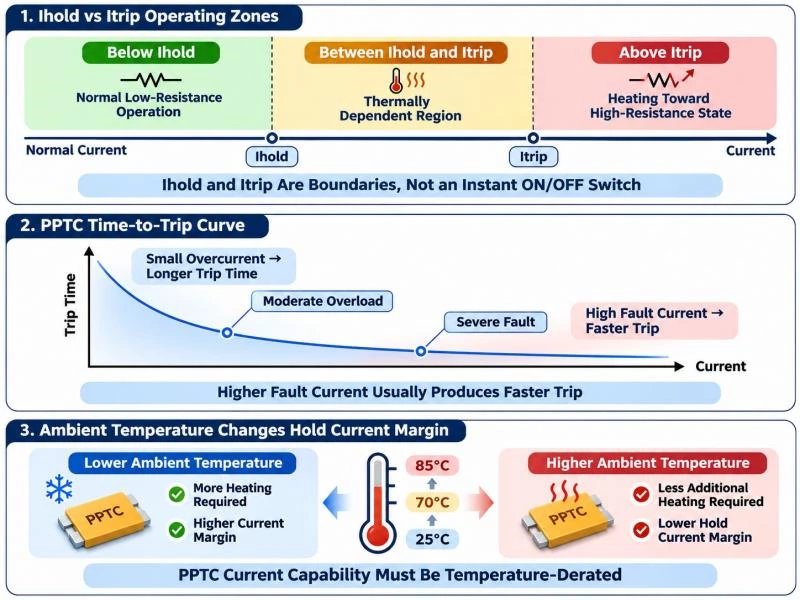
A PPTC specified with a particular Ihold at 25°C should not automatically be assumed to carry the same continuous current at 70°C or 85°C.
In higher-temperature environments, the usable hold current generally decreases, which is why PPTC datasheets normally include thermal derating information.
The practical design relationship is:
Maximum Normal Current < Temperature-Derated Hold Current
not simply:
Maximum Normal Current < 25°C Ihold
Temperature Also Affects Trip Time
Because the protection mechanism is thermal, ambient temperature can also influence how quickly the device reaches its high-resistance state during an overcurrent condition.
A warmer device begins closer to the temperature required for transition, while a colder device may take longer to accumulate the required heat.
This is one reason prototype validation should be performed at the real operating temperature rather than only on a laboratory bench at room temperature.
Ihold and Itrip Are Not the Same as Imax
Another common datasheet mistake is confusing Itrip with Imax.
They describe completely different limits.
| Parameter | Meaning |
|---|---|
| Ihold | Continuous current capability without tripping under specified conditions |
| Itrip | Current associated with transition toward the high-resistance state |
| Imax | Maximum fault current the device is rated to withstand under specified voltage conditions |
| Vmax | Maximum voltage allowed under the specified device conditions |
Imax is therefore not the current at which the PPTC trips.
For the PG16-050 example above:
Itrip = 1 A
while:
Imax = 40 A
The 40 A value describes fault-current withstand capability under the specified device rating, not a normal protection threshold.
How to Read a PPTC Datasheet Correctly
A PPTC datasheet should be read as a group of interacting parameters rather than as a single current rating.
A practical reading sequence is:
| Parameter | Question to Ask |
|---|---|
| Ihold | Can the device carry the maximum normal current at the real operating temperature? |
| Itrip | Is the protection region below the expected fault-current range? |
| Time-to-Trip | Will the device respond quickly enough to prevent unacceptable damage? |
| Vmax | Is the circuit voltage within the PPTC limit? |
| Imax | Can the device safely withstand the available fault current? |
| Rmin / R1max | Is the device resistance acceptable for voltage drop and power loss? |
This approach avoids the common mistake of choosing a PPTC only because its Ihold appears to match the load current.
Example: Normal Current, Startup Current and Fault Current
Consider a simplified circuit with the following operating profile:
| Condition | Current | Duration |
|---|---|---|
| Normal Operation | 0.8 A | Continuous |
| Startup Surge | 1.2 A | 200 ms |
| Fault | 3 A | Until protection operates |
It would be incorrect to select a PPTC simply by choosing Ihold = 0.8 A.
The designer should first determine whether the temperature-derated Ihold remains above 0.8 A. The 1.2 A startup event must then be checked against the device's time-current behavior to confirm that the PPTC does not nuisance-trip during normal startup.
At the 3 A fault condition, the time-to-trip must be fast enough to protect the downstream circuit before wiring, connectors, semiconductor devices, or other components exceed their allowable limits.
Vmax and Imax must also be checked independently.
A suitable PPTC must tolerate normal current and legitimate inrush while still responding quickly enough to the real fault condition.
Common Mistakes When Reading Ihold and Itrip
Treating Ihold as the Exact Trip Threshold
Ihold describes a continuous no-trip condition under specified conditions. It does not mean the PPTC will immediately enter protection when current rises slightly above Ihold.
Assuming Itrip Means Instantaneous Shutdown
PPTCs operate thermally. Even when the current is high enough to drive the device toward the tripped state, the transition requires time.
Ignoring the Region Between Ihold and Itrip
The current range between Ihold and Itrip should not be treated as a guaranteed operating or guaranteed trip region without consulting the relevant curves and conditions.
Ignoring Ambient Temperature
Using a 25°C Ihold value directly in a high-temperature enclosure can reduce design margin and may lead to nuisance tripping.
Confusing Imax with Itrip
Imax describes fault-current withstand capability. It is not the current at which the device is expected to enter its protective state.
Ignoring Startup or Inrush Current
Motors, capacitive inputs, communication interfaces, battery-powered devices and power converters can draw temporary current above the normal steady-state level. The PPTC must tolerate legitimate transient current without compromising fault protection.
How to Select Ihold and Itrip for a Real Application
1. Determine Maximum Normal Operating Current
Start with the highest continuous current the circuit is expected to draw during normal operation, including production tolerance and realistic load variation.
2. Apply Temperature Derating
Check the manufacturer's derating curve at the maximum expected ambient temperature. The resulting usable Ihold should remain above the required continuous current with reasonable margin.
3. Check Startup and Inrush Current
Determine the amplitude and duration of legitimate transient current. Compare the event with the PPTC's time-current behavior to avoid nuisance trips.
4. Check Fault Current and Time-to-Trip
Estimate the expected fault current and verify that the PPTC reaches its protective state quickly enough to protect downstream components.
5. Verify Vmax and Imax
The maximum circuit voltage must remain within Vmax, and the available fault current must remain within the PPTC's specified Imax capability.
6. Validate the Real Circuit
Finally, test the selected PPTC under actual PCB layout, ambient temperature, airflow, current profile, and fault conditions. Because PPTC behavior is thermally dependent, laboratory verification is especially important when design margins are narrow.
Prosemi PPTC Options
Prosemi provides PPTC options for both compact surface-mount circuits and through-hole applications.
The Low-R0 SMD Polymer PPTC Fuse family is designed for applications requiring compact footprints and low normal-state resistance. Available product data includes Ihold, Itrip, Vmax, Imax, time-to-trip, Rmin and R1max, allowing designers to compare normal-operation losses with protection performance.
For applications requiring through-hole mounting, Prosemi also provides DIP PPTC devices across multiple hold-current and voltage ranges.
Regardless of package type, the same selection principle applies: the correct PPTC should be chosen from the complete current, voltage, time and temperature profile of the application rather than from Ihold alone.
Conclusion
The difference between PPTC hold current and trip current is simple in definition but more complex in real circuit behavior.
Ihold defines the continuous operating side of the device, while Itrip describes the current region associated with the transition toward high resistance.
Neither value alone determines exactly when the PPTC will protect the circuit.
Reliable selection requires four factors to be considered together:
Ihold + Itrip + Time-to-Trip + Temperature
Vmax, Imax, resistance and the real fault-current profile should then be checked to ensure that the PPTC can operate safely in the intended circuit.
If you need help selecting a PPTC for a specific operating current, voltage, package size or fault condition, contact Prosemi for product selection and technical support.
FAQ
What is the difference between Ihold and Itrip in a PPTC?
Ihold is the maximum current the PPTC can continuously carry without tripping under specified conditions. Itrip is associated with the current condition that drives the device toward its high-resistance protective state.
What happens when current is between Ihold and Itrip?
The device is in a thermally dependent transition region. Its behavior depends on current level, duration, ambient temperature, thermal dissipation and the specific PPTC characteristics. The region should not be treated as a precise guaranteed trip threshold.
Does a PPTC trip immediately at Itrip?
No. PPTCs operate through self-heating, so the transition into the high-resistance state takes time. The actual trip time depends strongly on fault-current magnitude and temperature.
Is Ihold the same as a conventional fuse current rating?
Not exactly. Ihold describes the current a PPTC can continuously carry without tripping under specified thermal conditions. Because PPTCs are strongly temperature dependent, Ihold must be derated for the actual operating environment.
How does temperature affect PPTC hold current?
Higher ambient temperature generally reduces the available hold-current margin because the PPTC begins closer to the temperature required for its high-resistance transition. Designers should use the manufacturer's thermal derating information.
What is time-to-trip in a resettable fuse?
Time-to-trip is the time required for the PPTC to transition from its normal low-resistance state into its high-resistance protective state at a specified fault current and test condition.
What is the difference between Itrip and Imax?
Itrip relates to the PPTC's protective transition. Imax is the maximum fault current the device is rated to withstand under specified voltage conditions. Imax is not the trip threshold.
Does a PPTC completely open the circuit after tripping?
No. A PPTC enters a high-resistance state and limits current, but it does not normally create the complete open circuit produced by a conventional fuse after its element melts. A residual current may continue to flow.