How to Choose the Right Low Ohm Current Sense Resistor for High Precision Applications
Quick Answer (for engineers in a hurry)
A precision shunt resistor is selected based on four real constraints: TCR (<50 ppm/°C for EV), power dissipation (real copper conditions), Kelvin layout quality, and ADC voltage range. Ignore any one of these and your current reading drift can exceed 3–6% in real EV operation.
In real BMS and EV systems, low ohm current sense resistors are not just components—they are measurement references that define SOC accuracy, safety response, and system stability.
I’ve seen systems fail not because of “bad resistors”, but because the selection was done using datasheet thinking instead of system-level thinking.
1. What a Precision Shunt Resistor Really Does in EV Systems
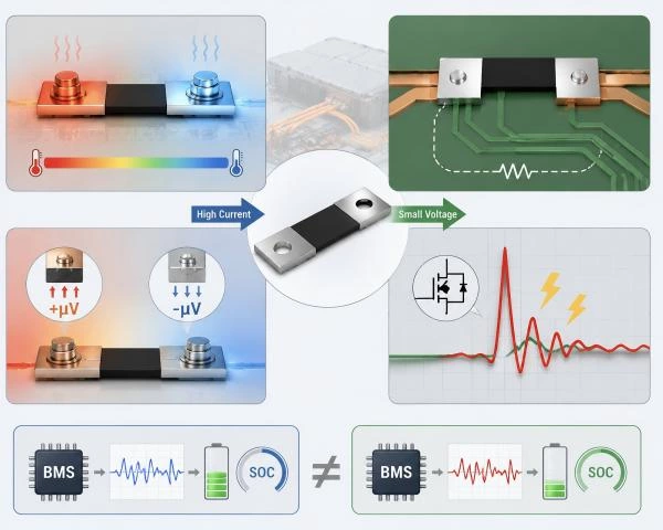
A precision shunt resistor converts current into voltage, but in EV environments, that signal is contaminated by:
- thermal gradients across terminals
- PCB trace parasitic resistance
- junction thermoelectric voltage
- switching noise (di/dt spikes)
That’s why two identical current sense resistor selection designs can produce completely different SOC behavior.
Related: Low Ohm Current Sense ResistorsBMS Resistor Solutions
2. TCR: The Hidden Factor That Breaks SOC Accuracy
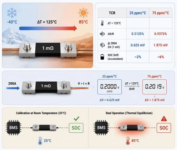
Why this matters: TCR is not a specification—it is a drift multiplier.
Assume a 1 mΩ resistor in EV battery pack:
Temperature swing: -40°C → 85°C (ΔT = 125°C)
- 25 ppm/°C → 0.3125% resistance change
- 75 ppm/°C → 0.9375% resistance change
At 200A, this translates into mV-level variation that accumulates into 2–6% SOC drift over time.
What trips most engineers: calibration at room temperature hides everything. Real drift appears under thermal equilibrium, not lab conditions.
3. Power Dissipation Is Not a Datasheet Number
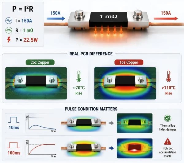
Why this matters: copper defines performance, not datasheet curves.
At 150A with 1 mΩ:
P = I²R = 22.5W
Now real PCB difference:
- 2oz copper → stable ~70°C rise
- 1oz copper → >110°C localized hotspot
Pulse condition matters more:
- 10ms → thermal lag hides damage
- 100ms → hotspot accumulation starts
Recommended Products:precision shunt resistor series
4. Thermal EMF: The Low Current Measurement Killer
Why this matters: below 1A, physics dominates electronics.
Thermal EMF at junctions: 0.2–3 µV/°C
At idle BMS current:
- Signal level: 5–15 mV
- Thermal noise: up to 300 µV
That’s already a 2–5% measurement distortion floor.
5. Parasitic Inductance and ADC Saturation Risk
Why this matters: EV switching edges are extremely fast.
V = L × di/dt
- 5 nH → 0.5V spike
- 10 nH → 1V spike
- 20 nH → 2V spike
This alone can saturate ADC front ends in BMS ICs (typical limit ~3.3V).
6. Kelvin Connection: Why 1 cm PCB Trace Can Break Your Current Measurement Accuracy
In real BMS and EV current sensing design, Kelvin connection (4-wire sensing) is not an optional optimization—it is a fundamental requirement for accuracy.
What most engineers underestimate is this: your PCB trace is part of the resistor system.
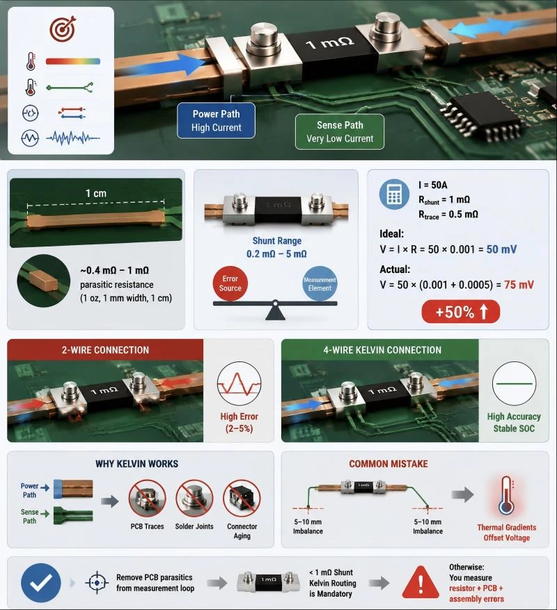
Why this matters: copper is not zero resistance
A typical PCB copper trace (1 oz, 1 mm width, 1 cm length) has approximately:
- 0.4 mΩ – 1 mΩ parasitic resistance depending on geometry
Now compare this with a typical shunt resistor:
- EV/BMS shunt range: 0.2 mΩ – 5 mΩ
You immediately see the problem:
Your “error source” is the same magnitude as your “measurement element”.
Real calculation example (what actually happens in field design)
Assume a 50A current measurement system:
- Shunt resistor: 1 mΩ
- PCB trace parasitic: 0.5 mΩ (1 cm routing mistake)
Ideal measurement voltage:V = I × R = 50 × 0.001 = 50 mV
Actual measurement voltage:V = 50 × (0.001 + 0.0005) = 75 mV
That is a +50% measurement error introduced purely by layout.
And yes—this happens more often than engineers admit during first prototypes.
2-wire vs 4-wire (Kelvin connection) reality
What trips most engineers: they think PCB routing is “just wiring”. It is not.
| Method | What it measures | Result |
|---|---|---|
| 2-wire connection | Resistor + PCB copper + solder joints | High error (2–5% typical) |
| 4-wire Kelvin connection | Only resistor voltage drop | High accuracy, stable SOC |
In EV validation tests, 2-wire layouts often show: 2% to 5% deviation under load, even with precision resistors.
Why Kelvin connection actually works
Kelvin sensing separates two paths:
- Power path: carries high current
- Sense path: carries almost zero current
This eliminates voltage drop influence from:
- PCB traces
- Solder joints
- Connector aging
That’s why proper current sense resistor PCB layout always uses dedicated sense pads close to the resistor body.
Common real-world mistake (very important)
Wrong assumption: “I routed sense lines close enough, it should be fine.”
In reality:
- Even 5–10 mm routing imbalance can introduce micro-ohm mismatch
- Thermal gradients between traces create additional offset voltage
This leads to a hidden failure mode:
stable lab calibration → unstable field SOC behavior
Engineering takeaway
Kelvin connection is not about “best practice”. It is about removing PCB parasitics from the measurement loop entirely.
If your system uses a low ohm current sense resistor below 1 mΩ, Kelvin routing is not optional—it is mandatory.
Otherwise, you are no longer measuring current. You are measuring: resistor + PCB + assembly errors.
7. Real Engineering Selection Flow (Used in Industry)
In real EV and BMS hardware design, current sense resistor selection is never a single-parameter decision. Engineers don’t start from “which resistor to use”, they start from system constraints.
What actually works in industry is a step-by-step constraint reduction process. Each step removes one layer of uncertainty until only one viable resistor architecture remains.
Step 1: Define maximum continuous current → determines package and thermal structure
This is the true starting point. Not resistance value.
Ask first: what is the worst-case continuous current, not nominal current?
- Below 50A → standard metal strip or chip shunt possible
- 50A–200A → low-ohm metal element / busbar shunt required
- 200A+ → copper bar / integrated shunt architecture
What trips most engineers: designing for “average current” instead of thermal worst-case current. That leads directly to long-term drift and solder fatigue.
Step 2: Define thermal environment → selects TCR grade and stability class
Why this matters: TCR is not a precision parameter—it is a system drift multiplier.
In EV environments, junction temperature is often underestimated. A “70°C ambient system” can easily reach:
- 95–110°C PCB hotspot
- 120°C+ at shunt terminals under load
At this point:
- 25 ppm/°C → acceptable for high precision SOC tracking
- 50–75 ppm/°C → acceptable for protection-level monitoring only
Here’s the catch: many designs fail not because resistor is wrong, but because TCR is selected based on ambient temperature, not junction temperature.
Step 3: Define ADC full-scale range → determines resistance value (mΩ optimization)
Why this matters: your resistor value is constrained by your ADC, not theory.
Typical BMS current sense chain:
- Shunt voltage target: 25 mV – 100 mV full scale
- ADC input range: 50 mV – 250 mV (after amplification)
Example:
If max current = 200A and target shunt voltage = 50 mV:
R = V / I = 0.05 / 200 = 0.25 mΩ
Now the trade-off appears:
- Lower R → better efficiency, worse signal resolution
- Higher R → better resolution, worse thermal loss
This is where most “paper designs” fail—they ignore ADC front-end limitations and gain staging.
Step 4: Define surge current → determines mechanical + thermal reinforcement design
Why this matters: transient current kills more shunts than steady-state current.
In EV systems, surge events can reach:
- 2× to 5× nominal current during startup or fault conditions
- di/dt spikes during switching events (>100 A/µs)
At this stage, design focus shifts from electrical to electro-thermal-mechanical coupling:
- pad size and solder thickness
- copper plane reinforcement
- thermal via distribution
- stress relief routing
What trips most engineers: assuming “if it survives steady current, it survives surge current”. In reality, surge defines fatigue life, not steady-state does.
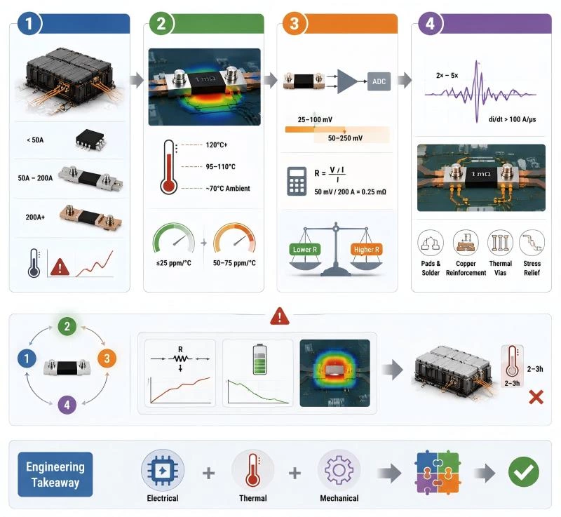
Cross-step dependency (why Step 2 is the real failure point)
Most design failures don’t happen in Step 1 or Step 4. They happen in Step 2.
Why? Because TCR interacts with everything:
- It modifies effective resistance under load (Step 3 mismatch)
- It shifts SOC integration accuracy over time
- It amplifies thermal gradient error across PCB layout
In field validation, we often see systems that pass electrical design but fail thermal equilibrium testing after 2–3 hours continuous operation.
That’s not a component issue. That’s a thermal model mismatch issue.
Final engineering insight
A proper current sense resistor selection is not a component choice—it is a constraint-solving process across electrical, thermal, and mechanical domains.
If you only optimize one parameter (like resistance value or power rating), the system will eventually drift somewhere else—usually SOC accuracy or thermal stability.
8. Common Real-World Failure Cases
Case 1 — "High-precision resistor, but SOC keeps drifting."
We swapped resistors. Three different suppliers. Same result. Root cause: the PCB copper surface had oxidized after thermal cycling. Contact resistance at the solder joint changed over time. The resistor was fine. The joint wasn't.
Case 2 — "Calibrated perfectly in the lab. Fails in the vehicle."
Lab calibration at 25°C. Vehicle at 60°C steady state. System offset drifted 3–4%. TCR + layout asymmetry combined. Fix: matched the thermal expansion of both sense traces. Symmetric routing. Problem gone.
Case 3 — "Low-current noise drives us crazy."
ADC was clean. Software filtering was aggressive. Problem persisted. Two days of debugging: thermal EMF from a ground loop. The Kelvin sense return path shared a ground with the main power return. Moved the return to a dedicated star ground. Noise disappeared.
Every single time, the resistor was not at fault.
Need Engineering Support?
As a current sense resistor manufacturer, we provide custom low-ohm solutions for EV, BMS, and energy storage systems.
Request technical support or quotation →
FAQ
What is a precision shunt resistor used for?
It is used for high accuracy current measurement in EV, BMS, and power electronics systems.
How do I choose a current sense resistor for BMS?
Based on current range, thermal environment, ADC range, and required accuracy under real operating temperature.
What causes current measurement drift in EV systems?
Main causes include TCR drift, PCB parasitic resistance, thermal EMF, and layout errors.
Why is Kelvin connection important?
It removes copper trace resistance from measurement, improving accuracy by several percent in high current systems.
Quick Reference Table
| Parameter | Recommended | Risk if ignored |
|---|---|---|
| TCR | ≤50 ppm/°C | SOC drift 2–6% |
| Resistance | 0.2–5 mΩ | ADC saturation or low resolution |
| Layout | 4-wire Kelvin | 2–5% error |
| Copper | ≥2oz | thermal runaway |