PR250-009
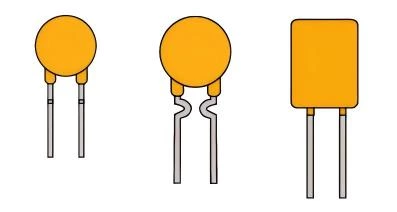
Radial Leaded | Round/Square size
Polymer Positive Temperature Coefficient Thermistor
Features
- Low voltage over-current protection
- Working current: 0.03A-2.0A
- Impulse voltage: 250V
- In line with RoHS certification, halogen-free product
- Tinned copper clad steel wire(0.03~1.4A)/ Tinned Copper wire(2.0A)
Electrical Performance
| Product model | IH (A) |
IT (A) |
Vmax (V) |
Imax (A) |
Max Time Trip | Pd typ (W) |
RMin (Ω) |
R1Max (Ω) |
|
|---|---|---|---|---|---|---|---|---|---|
| (A) | (S) | ||||||||
| PR250-003 | 0.03 | 0.08 | 250 | 3 | 0.15 | 10.0 | 1.0 | 40.00 | 153.00 |
| PR250-004 | 0.04 | 0.12 | 250 | 3 | 0.20 | 10.0 | 1.0 | 33.00 | 110.50 |
| PR250-005 | 0.05 | 0.12 | 250 | 3 | 0.25 | 10.0 | 1.0 | 24.00 | 102.00 |
| PR250-006 | 0.06 | 0.12 | 250 | 3 | 0.30 | 10.0 | 1.0 | 22.00 | 54.40 |
| PR250-008 | 0.08 | 0.16 | 250 | 3 | 0.40 | 10.0 | 1.0 | 14.00 | 37.40 |
| PR250-009 | 0.09 | 0.18 | 250 | 3 | 0.45 | 10.0 | 1.0 | 10.00 | 34.00 |
| PR250-011 | 0.11 | 0.22 | 250 | 3 | 0.55 | 15.0 | 1.0 | 7.00 | 18.70 |
| PR250-012 | 0.12 | 0.24 | 250 | 3 | 0.60 | 15.0 | 1.0 | 8.00 | 20.40 |
| PR250-0145 | 0.145 | 0.29 | 250 | 3 | 0.725 | 15.0 | 1.0 | 3.50 | 11.05 |
| PR250-018 | 0.18 | 0.50 | 250 | 3 | 0.90 | 15.0 | 1.5 | 0.80 | 5.10 |
| PR250-020 | 0.20 | 0.40 | 250 | 3 | 1.00 | 15.0 | 1.5 | 1.50 | 5.44 |
| PR250-030 | 0.30 | 0.60 | 250 | 3 | 1.50 | 15.0 | 1.5 | 0.90 | 2.38 |
| PR250-035 | 0.35 | 0.70 | 250 | 3 | 1.75 | 10.0 | 1.5 | 0.80 | 2.55 |
| PR250-040 | 0.40 | 0.80 | 250 | 3 | 2.00 | 10.0 | 2.5 | 0.75 | 1.87 |
| PR250-050 | 0.50 | 1.00 | 250 | 5 | 2.50 | 15.0 | 3.0 | 0.50 | 1.36 |
| PR250-060 | 0.60 | 1.20 | 250 | 5 | 3.00 | 10.0 | 3.0 | 0.50 | 1.275 |
| PR250-080 | 0.80 | 1.60 | 250 | 5 | 4.00 | 10.0 | 3.5 | 0.45 | 1.05 |
| PR250-100 | 1.00 | 2.00 | 250 | 5 | 5.00 | 10.0 | 4.0 | 0.28 | 0.765 |
| PR250-120 | 1.20 | 2.40 | 250 | 10 | 6.00 | 15.0 | 4.2 | 0.17 | 0.42 |
| PR250-140 | 1.40 | 2.80 | 250 | 10 | 7.00 | 20.0 | 4.5 | 0.18 | 0.375 |
| PR250-200 | 2.00 | 4.00 | 250 | 10 | 10.0 | 25.0 | 5.0 | 0.12 | 0.285 |
IH= Hold current: maximum current at which the device will not trip at 23℃ still air.
IT= Trip current: minimum current at which the device will always trip at 23℃ still air.
Vmax= Maximum continuous voltage device can withstand without damage at rated current
Imax= Maximum fault current device can withstand without damage at rated voltage.
Ttrip= Maximum time to trip(s) at assigned current.
Pdtyp=Typical power dissipation: typical amount of power dissipated by the device when in state air environment.
Rmin= Minimum resistance of device in initial (un-soldered) state.
R1max= Maximum resistance of device at 23℃ measured one hour after reflow.
Noted: All electrical function test is conducted after PCB mounted.
Thermal Derating Chart
Hold Current (A)
| Part Number | Ambient Operating Temperature | ||||||||
|---|---|---|---|---|---|---|---|---|---|
| -40°C | -20°C | 0°C | 23°C | 40°C | 50°C | 60°C | 70°C | 85°C | |
| PR250-003 | 0.047 | 0.041 | 0.036 | 0.030 | 0.025 | 0.022 | 0.019 | 0.016 | 0.012 |
| PR250-004 | 0.063 | 0.055 | 0.048 | 0.040 | 0.033 | 0.029 | 0.026 | 0.022 | 0.016 |
| PR250-005 | 0.079 | 0.069 | 0.060 | 0.050 | 0.042 | 0.037 | 0.032 | 0.027 | 0.020 |
| PR250-006 | 0.095 | 0.083 | 0.071 | 0.060 | 0.050 | 0.044 | 0.038 | 0.032 | 0.024 |
| PR250-008 | 0.126 | 0.110 | 0.095 | 0.080 | 0.066 | 0.058 | 0.051 | 0.043 | 0.032 |
| PR250-009 | 0.142 | 0.124 | 0.107 | 0.090 | 0.075 | 0.066 | 0.058 | 0.049 | 0.036 |
| PR250-011 | 0.174 | 0.152 | 0.131 | 0.110 | 0.091 | 0.080 | 0.070 | 0.059 | 0.044 |
| PR250-012 | 0.190 | 0.166 | 0.143 | 0.120 | 0.100 | 0.088 | 0.077 | 0.065 | 0.048 |
| PR250-0145 | 0.229 | 0.200 | 0.173 | 0.145 | 0.120 | 0.106 | 0.093 | 0.078 | 0.058 |
| PR250-018 | 0.284 | 0.248 | 0.214 | 0.180 | 0.149 | 0.131 | 0.115 | 0.097 | 0.072 |
| PR250-020 | 0.316 | 0.274 | 0.238 | 0.200 | 0.166 | 0.146 | 0.128 | 0.108 | 0.080 |
| PR250-030 | 0.474 | 0.414 | 0.357 | 0.300 | 0.249 | 0.219 | 0.192 | 0.162 | 0.120 |
| PR250-035 | 0.553 | 0.483 | 0.417 | 0.350 | 0.291 | 0.256 | 0.224 | 0.189 | 0.140 |
| PR250-040 | 0.632 | 0.552 | 0.476 | 0.400 | 0.332 | 0.292 | 0.256 | 0.216 | 0.160 |
| PR250-050 | 0.790 | 0.690 | 0.595 | 0.500 | 0.415 | 0.365 | 0.320 | 0.270 | 0.200 |
| PR250-060 | 0.948 | 0.828 | 0.714 | 0.600 | 0.498 | 0.438 | 0.384 | 0.324 | 0.240 |
| PR250-080 | 1.264 | 1.104 | 0.952 | 0.800 | 0.664 | 0.584 | 0.512 | 0.432 | 0.320 |
| PR250-100 | 1.580 | 1.380 | 1.190 | 1.000 | 0.830 | 0.730 | 0.640 | 0.540 | 0.400 |
| PR250-120 | 1.896 | 1.656 | 1.428 | 1.200 | 0.996 | 0.876 | 0.768 | 0.648 | 0.480 |
| PR250-140 | 2.212 | 1.932 | 1.666 | 1.400 | 1.162 | 1.022 | 0.896 | 0.756 | 0.560 |
| PR250-200 | 3.160 | 2.760 | 2.380 | 2.000 | 1.660 | 1.460 | 1.280 | 1.080 | 0.800 |
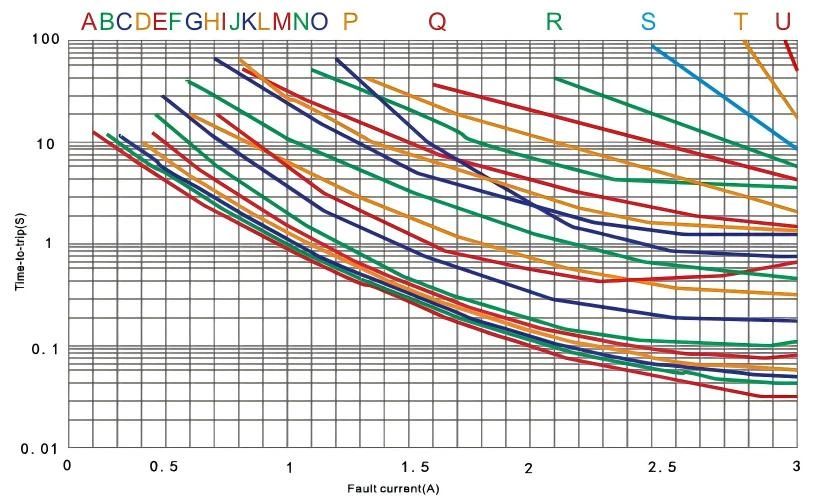
Typical time to trip at 23˚C
A=PR250-003
B=PR250-004
C=PR250-005
D=PR250-006
E=PR250-008
F=PR250-009
G=PR250-011
H=PR250-012
I=PR250-0145
J=PR250-018
K=PR250-020
L=PR250-030
M=PR250-035
N=PR250-040
O=PR250-050
P=PR250-060
Q=PR250-080
R=PR250-100
S=PR250-120
T=PR250-140
U=PR250-200
Electrical Performance

Size(mm)
| Product model |
A | B | C | D | E | F | Lead | FIG | Package QTY |
|---|---|---|---|---|---|---|---|---|---|
| max | max | typ | min | max | typ | Φ | |||
| PR250-003 | 7.00 | 12.80 | 5.10 | 7.60 | 4.40 | / | 0.60 | 1 | 1000PCS |
| PR250-004 | 7.00 | 12.80 | 5.10 | 7.60 | 4.40 | / | 0.60 | 1 | 1000PCS |
| PR250-005 | 7.00 | 12.80 | 5.10 | 7.60 | 4.40 | / | 0.60 | 1 | 1000PCS |
| PR250-006 | 7.00 | 12.80 | 5.10 | 7.60 | 4.40 | / | 0.60 | 1 | 1000PCS |
| PR250-008 | 7.00 | 12.80 | 5.10 | 7.60 | 4.40 | / | 0.60 | 1 | 1000PCS |
| PR250-009 | 7.00 | 12.80 | 5.10 | 7.60 | 4.40 | / | 0.60 | 1 | 1000PCS |
| PR250-011 | 7.00 | 13.50 | 5.10 | 7.60 | 4.40 | / | 0.60 | 2 | 1000PCS |
| PR250-012 | 7.00 | 13.50 | 5.10 | 7.60 | 4.40 | / | 0.60 | 2 | 1000PCS |
| PR250-0145 | 7.00 | 13.50 | 5.10 | 7.60 | 4.40 | / | 0.60 | 2 | 1000PCS |
| PR250-018 | 9.00 | 15.50 | 5.10 | 7.60 | 4.40 | / | 0.60 | 1 | 1000PCS |
| PR250-020 | 9.00 | 15.50 | 5.10 | 7.60 | 4.40 | / | 0.60 | 1 | 1000PCS |
| PR250-030 | 9.00 | 15.50 | 5.10 | 7.60 | 4.40 | / | 0.60 | 1 | 1000PCS |
| PR250-035 | 9.50 | 15.50 | 5.10 | 7.60 | 4.40 | 2.20 | 0.60 | 1 | 1000PCS |
| PR250-040 | 10.00 | 16.40 | 5.10 | 7.60 | 4.40 | 2.20 | 0.60 | 4 | 500PCS |
| PR250-050 | 11.00 | 15.80 | 5.10 | 7.60 | 4.40 | 2.20 | 0.80 | 3 | 500PCS |
| PR250-060 | 11.00 | 15.80 | 5.10 | 7.60 | 4.40 | 2.20 | 0.80 | 3 | 500PCS |
| PR250-080 | 11.00 | 15.80 | 5.10 | 7.60 | 4.40 | 2.20 | 0.80 | 3 | 500PCS |
| PR250-100 | 14.00 | 19.10 | 5.10 | 7.60 | 4.40 | 2.20 | 0.80 | 3 | 500PCS |
| PR250-120 | 16.00 | 21.00 | 5.10 | 7.60 | 4.40 | 2.20 | 0.80 | 3 | 500PCS |
| PR250-140 | 17.10 | 21.60 | 5.10 | 7.60 | 4.40 | 2.20 | 0.80 | 3 | 500PCS |
| PR250-200 | 21.00 | 25.00 | 10.20 | 7.60 | 4.40 | 2.20 | 0.80 | 5 | 200PCS |
Regular Service Condition
1. Operating ambient temperature:-40℃~85℃.
2. Exceeding the applicable conditions of this product or other improper use may cause damage, or even cause electric breakdown or flame.
3. PPTC components are designed for occasional over-current in the circuit and are not recommended for continuous and continuous over current circuits.
4. Avoid contact of PPTC components with chemical solvents. Prolonged contact will damage the performance of the components.