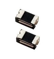
SRF0402P035LR
Surface-Mount Devices | 0402
Size PTC Resettable Fuses
Features
- Resettable over current and over temperature protection Standard 0402mils footprint
- Fast time-to-trip
- RoHS complaint
- Low resistance
Applications
- USB peripherals including new USB 3.0 / 2.0 ports
- Li-ion / Li-Polymer battery packs
- Smart phones
- E-readers
- LCD / LED HDTV Tablet , Notebook PCs and Computer peripherals Digital cameras and video cameras
- Hard disk drives
- Game consoles
Electrical Characteristics
| Part Number | IH (A) |
IT (A) |
Vmax (V) |
Imax (A) |
Time to Trip | Pdtyp (W) |
R min (Ω) |
R1max (Ω) |
|
|---|---|---|---|---|---|---|---|---|---|
| (A) | (Sec.) | ||||||||
| SRF0402P010LR | 0.10 | 0.30 | 6 | 50 | 0.50 | 1.00 | 0.50 | 0.150 | 2.000 |
| SRF0402P020LR | 0.20 | 0.50 | 6 | 50 | 1.00 | 1.00 | 0.50 | 0.100 | 1.250 |
| SRF0402P035LR | 0.35 | 0.70 | 6 | 50 | 8.00 | 1.00 | 0.50 | 0.050 | 0.700 |
| SRF0402P050LR | 0.50 | 1.00 | 6 | 50 | 8.00 | 1.00 | 0.50 | 0.040 | 0.400 |
| SRF0402P100LR | 1.00 | 2.00 | 6 | 50 | 8.00 | 5.00 | 0.50 | 0.250 | 0.250 |
IH=Hold current: maximum current at which the device will not trip at 25℃ still air.
IT=Trip current: minimum current at which the device will always trip at 25℃ still air.
Vmax=Maximum continuous voltage device can withstand without damage at rated current
Imax=Maximum fault current device can withstand without damage at rated voltage.
Ttrip=Maximum time to trip(s) at assigned current.
Pdtyp=Typical power dissipation: typical amount of power dissipated by the device when in state air environment.
Rmin=Minimum resistance of device in initial (un-soldered) state.
R1max=Maximum resistance of device at 25℃ measured one hour after reflow.
Noted: All electrical function test is conducted after PCB mounted.
Thermal Derating Chart
Hold Current (A)
| Part Number | Ambient Operating Temperature (Holding Current in A) | ||||||||
|---|---|---|---|---|---|---|---|---|---|
| -40°C | -20°C | 0°C | 25°C | 40°C | 50°C | 60°C | 70°C | 85°C | |
| SRF0402P010LR | 0.15 | 0.13 | 0.12 | 0.10 | 0.09 | 0.08 | 0.07 | 0.06 | 0.05 |
| SRF0402P020LR | 0.26 | 0.24 | 0.22 | 0.20 | 0.16 | 0.14 | 0.12 | 0.10 | 0.07 |
| SRF0402P035LR | 0.46 | 0.42 | 0.39 | 0.35 | 0.28 | 0.25 | 0.21 | 0.18 | 0.12 |
| SRF0402P050LR | 0.65 | 0.60 | 0.55 | 0.50 | 0.40 | 0.35 | 0.30 | 0.25 | 0.17 |
| SRF0402P100LR | 1.25 | 1.18 | 1.10 | 1.00 | 0.90 | 0.80 | 0.70 | 0.60 | 0.50 |
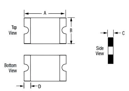
Dimensions (mm)
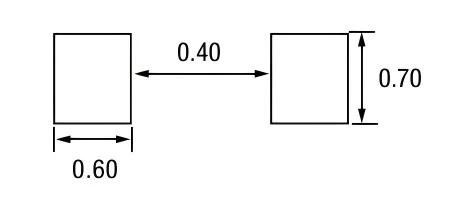
Recommended Pad Layout (mm)
| Part Number | Marking | A | B | C | D | |||
|---|---|---|---|---|---|---|---|---|
| Min. | Max. | Min. | Max. | Min. | Max. | Min. | ||
| SRF0402P010LR | White | 0.95 | 1.25 | 0.45 | 0.75 | 0.30 | 0.60 | 0.10 |
| SRF0402P020LR | Yellow | 0.95 | 1.25 | 0.45 | 0.75 | 0.35 | 0.65 | 0.10 |
| SRF0402P035LR | Black | 0.95 | 1.25 | 0.45 | 0.75 | 0.30 | 0.60 | 0.10 |
| SRF0402P050LR | Green | 0.95 | 1.25 | 0.45 | 0.75 | 0.40 | 0.60 | 0.10 |
| SRF0402P100LR | Red | 0.95 | 1.25 | 0.45 | 0.75 | 0.30 | 0.60 | 0.10 |
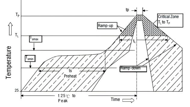
Solder Reflow Conditions
| Reflow Profile | Lead free |
|---|---|
| Heating rate from Tsmax to Tp | Max. 3℃/second |
| Pre-heat: Tsmin Tsmax Tsmin to Tsmax |
150℃ 200℃ 60~180 seconds |
| Soldering time: Temperature (TL) Time (tL) |
>217℃ 60~150 seconds |
| Peak temperature (Tp) | 260℃ |
| Time at Peak temperature ±5℃ (tp) | 20~40 seconds |
| Cooling rate | Max. 6℃/second |
| Time from 25℃ to Peak Temperature | 8 minutes max |
Cautions for Reflow:
1. Recommended reflow methods: IR, hot air oven, nitrogen oven;
2. The printed solder thickness is not over 0.25mm,Excess solder may cause a short circuit, especially during hand soldering;
3. If reflow temperatures exceed the recommended profile, devices may not meet the performance requirements;
4. Device can not be wave soldered. Please contact Prosemi for hand soldering and dip soldering recommendations;
5. Device can’t contact solvent;
Note:All temperature in top chart is measured on the surface of devices.
Packaging Options
| I hold(A) | Quantity |
|---|---|
| 0.10~1.00 | 10,000pcs |