ALMJ20 Current Sensing Resistor
Description
- Thick copper conductor metallized material. . Ultra long term stability.
- Halogen-free and lead-free RoHS compliant.
- Stable materials.
- Excellent trustworthiness.
- High power rating.
- Ultra-low temperature drift (good TCR).
Part Numbering System
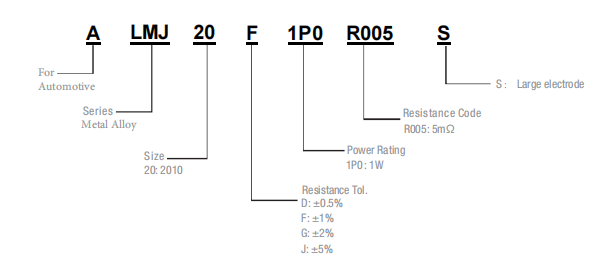
| Parameter | Standard |
|---|---|
| Power Rating | 1 & 1.5 W |
| Resistance Value | 1 ~ 100 mΩ |
| Operating Temperature Range | -55 to +170 °C |
Rated Current = (P / R)1/2;
P=Power Rating,R=Resistance Value.
Standard Electrical Specifications
| Type | Rating Power at 70℃ | T.C.R. (ppm/℃) | Resistance Range (mΩ) 0.5%(D) 1.0%(F) 2.0%(G) 5.0%(J) | Material | Operating Temperature (℃) |
|---|---|---|---|---|---|
| ALMJ20 | 1 & 1.5 W | ±50 | 1~3mΩ :S 1~100mΩ | Metal Alloy | -55 ~ +170°C |
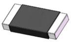
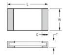
construction
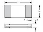
Unit: mm
| Type | Resistance (mΩ) | L (mm) | W (mm) | C (mm) | T (mm) |
|---|---|---|---|---|---|
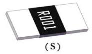
| ALMJ20-S | 1 ~ 3 | 5.0 ±0.2 | 2.5 ±0.2 | 1.5 ±0.3 | 0.6 ±0.2 |
Unit: mm
| Type | Resistance (mΩ) | L (mm) | W (mm) | C (mm) | T (mm) |
|---|---|---|---|---|---|
| ALMJ20 | 1 ~ 100 | 5.0 ±0.2 | 2.5 ±0.2 | 1.5 ±0.3 | 0.6 ±0.2 |
Recommended land pattern
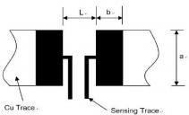
Unit: mm
| Type | Resistance (mΩ) | a (mm) | b (mm) | L (mm) |
|---|---|---|---|---|
| ALMJ20 | 1 ~ 100 | 3.4 ±0.2 | 1.5 ±0.2 | 3.5 ±0.2 |
| ALMJ20-S | 1 ~ 3 | 3.4 ±0.3 | 3.5 ±0.2 | 2.0 ±0.2 |
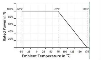
Power Derating Curve
For resistors operated in ambient temperatures 70°C,power ratingshall bederated inaccording with the curve below
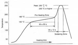
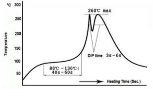
IR Reflow-Soldering Profile
Wave- Soldering Profile
Product Characteristics
| Item | Test Condition / Methods | Limit | Standard |
|---|---|---|---|
| Temperature Coefficient of Resistance (TCR) | TCR = (R - R0) / R0(T2 - T1) × 10⁶R0: resistance at room tempR: resistance at 125℃T1: room tempT2: 125℃ | Refer to Spec | JIS-C 5201 |
| Short Time Overload | 5 × rated power for 5 seconds | ≤ ±0.5% | JIS-C5201-1 4.13 |
| Temperature Cycling | 1000 cycles (-55℃ to 125℃), 30 min at each extreme | ≤ ±0.5% | JESD22 Method JA-104 |
| Low Temperature Storage | -55℃ for 1000 hours, no power | ≤ ±0.5% | JIS C 5201 |
| High Temperature Storage | 1000 hours at 125℃,No power | ≤ ±1% | MIL-STD-202 Method 108 |
| Biased Humidity | 85℃±5℃, 85±5% RH 10% bias, 1000 hours ,at rated power 1.5 hours “ON”, 0.5 hours “OFF” , after standing 24±4 hours to measure the resistance change rate. | ≤ ±0.5% | MIL-STD-202 Method 103 |
| Operational Life | Apply the rated current to the 125±3℃ incubator for 1000 hours, and stand for 24±4 hours after removal to measure the resistance change rate. | ≤ ±0.5% | MIL-STD-202 Method 108 |
| Load Life | 70℃± 2℃, 1000 hours, at rated power 1.5 hours “ON”, 0.5 hours “OFF” , after taking it out and standing for more than 1 hour, the resistance change rate is measured. | ≤ ±1% | JIS-C5201 |
| Resistance to Solder Heat | 260℃± 5℃, time:10 ±1 sec, 1000 hours, after taking out and standing for more than 1 hour, measure the resistance change rate. | ≤ ±0.5% | MIL-STD-202 Method 210 |
| Solderability | Soak in the furnace at 245±5℃ for 3±1 sec .Take out and observe the solder area under amagnifying alass. | Solder coverage ≥95%, no damage | J-STD-002 |
| Joint Strength of Solder | ◆ Test item (Bendability test) Weld in the bending test plate, place on the bending test machine, press in the center of the test plate, and measure under load. | ≤ ±0.5% | JIS-C5201-1 4.32 |
| ◆ Experiment item 2 (Fixation test) Weld the resistance in the rigidity test plate, place it on the end electrode test machine, apply the force in the direction of the force with the test probe with the radius of R0.5, and maintain 10 sec, andmeasure the resistance change rate under the load. | ≤ ±0.5% | JIS-C5201-1 4.32 |
Tapping & Package
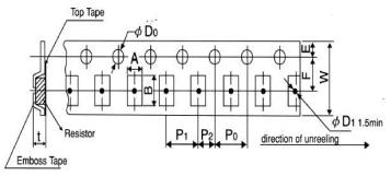
Unit: mm
| Type | Pack | A ±0.2 | B ±0.2 | D0 +0.5/-0 | E ±0.1 | F ±0.05 | P0 ±0.1 | P1 ±0.1 | P2 ±0.1 | W ±0.2 | D1 ±0.05 | T ±0.15 |
|---|---|---|---|---|---|---|---|---|---|---|---|---|
| 2010 | Emboss | 2.80 | 5.30 | 1.50 | 1.75 | 5.50 | 4.00 | 4.00 | 2.00 | 12.00 | 1.50 | 0.85 |
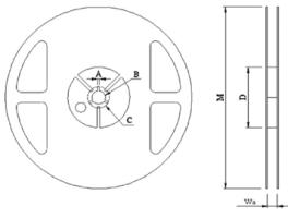
Reel Specification
Unit: mm
| Type | A | B | C | D | M | W |
|---|---|---|---|---|---|---|
| 2010 | 2.00 ±0.5 | 13.5±0.5 | 21.00±0.5 | 60.00 ±1.0 | 178.00±2.0 | 13.80±0.5 |
Packaging
Quantity: 4, 000pcs