LMJ12 Current Sense Resistor
Products Specifications
- Package
- 1206
- Features
- Current Sense, Industrial Grade, Extremely Low Resistance Values, Very Low Inductance, Low Thermal EMF
- Series
- LMJ12
- Operating Temperature
- -55℃ ~ +170℃
- Temperature Coefficient
- ±50ppm/°C
- Resistance
- 160 mOhms
- Power Rating
- 0.5W
- Tolerance
- 1%
- Mounting
- SMD / SMT
- Style
- Surface Mount Current Sensing Reistors
- Termination
- 2-Terminal
- Composition
- Metal Alloy
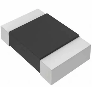
Description
- Proprietary processing technique produces extremely low resistance values
- Very low inductance
- Low thermal EMF
- Metallic Material
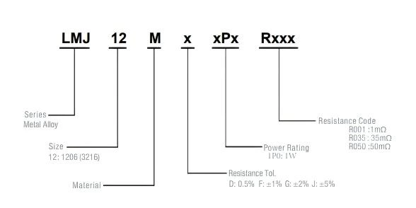
Part Numbering System
| Parameter | Standard |
|---|---|
| Power Rating | 0.5W & 1W |
| Resistance Value | 1mΩ ~ 200mΩ |
| Operating Temperature Range | -55 to + 170°C |
| Component Temperature Coefficient (TCR) | ± 50ppm/°C |
| Maximum Working Voltage (V) | (P×R)1/2 |
| Rating Current (A) | (P/R)1/2 |
P=Power Rating; R=Resistance Value
Standard Electrical Specifications
| Type | Rating Power at 70℃ |
T.C.R. (ppm/℃) |
Resistance Range(mΩ) 0.5%(D),1.0%( F) 2.0%(G),5.0%(J) |
Meterial | Electrode | Operating Temperature(℃) |
|---|---|---|---|---|---|---|
| LMJ12 | 1W | 50 | 1~100 | R001~R100: MnCu | R001~R100 | -55~+170℃ |
| 0.5W | 50 | 101~200 | R101~R200: MnCu | R101~R200 |
Resistance Values of the 1206 Series, 1W Resistors
| Standard Resistance Values ( Ω ) | ||||||||||||
|---|---|---|---|---|---|---|---|---|---|---|---|---|
| 0 ohm | 0.001 ohm | 0.002 ohm | 0.003 ohm | 0.005 ohm | 0.01 ohm | 0.015 ohm | 0.02 ohm | 0.025 ohm | 0.03 ohm | 0.04 ohm | 0.05 ohm | 0.1 ohm |
| R000 | R001 | R002 | R003 | R005 | R010 | R015 | R020 | R025 | R030 | R040 | R050 | R100 |
| Manufacturable Resistance Values ( Ω ) | ||||||||||||
|---|---|---|---|---|---|---|---|---|---|---|---|---|
| 0.0015 ohm | 0.0025 ohm | 0.004 ohm | 0.0048 ohm | 0.006 ohm | 0.007 ohm | 0.008 ohm | 0.009 ohm | 0.011 ohm | 0.012 ohm | 0.013 ohm | 0.014 ohm | 0.018 ohm |
| R0015 | R0025 | R004 | R0048 | R006 | R007 | R008 | R009 | R011 | R012 | R013 | R014 | R018 |
| 0.022 ohm | 0.024 ohm | 0.027 ohm | 0.033 ohm | 0.035 ohm | 0.039 ohm | 0.045 ohm | 0.047 ohm | 0.06 ohm | 0.068 ohm | 0.07 ohm | 0.075 ohm | 0.08 ohm |
| R022 | R024 | R027 | R033 | R035 | R039 | R045 | R047 | R060 | R068 | R070 | R075 | R080 |
| 0.082 ohm | 0.09 ohm | —— | ||||||||||
| R082 | R090 | |||||||||||
Dimensions
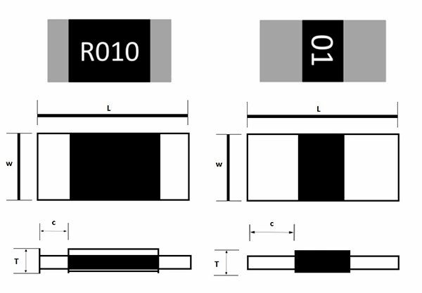
Unit: Millimeters
| Type | Resistance Range (mΩ) |
L | W | C | T |
|---|---|---|---|---|---|
| LMJ 12 | 1 | 3.2 ±0.2 | 1.6 ±0.2 | 1.2 ±0.2 | 0.7± 0.15 |
| 2~200 | 3.2 ±0.2 | 1.6 ±0.2 | 0.5±0.2 | 0.7± 0.15 |
Recommended land pattern
Unit: Millimeters
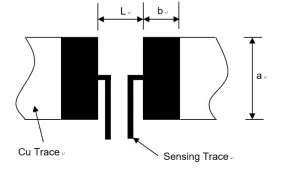
| Resistance Range ( mΩ ) | a | b | L |
|---|---|---|---|
| 1 | 1.8±0.1 | 2.3±0.1 | 1.0±0.1 |
| 2~200 | 1.8±0.1 | 1.7±0.1 | 1.6±0.1 |
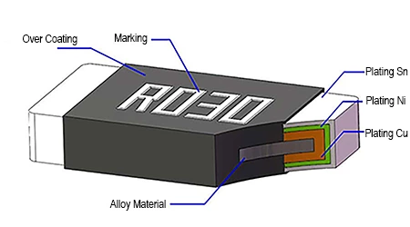
Product structure diagram
Product Characteristics
| Item | Test condition | Limited | Standard |
|---|---|---|---|
| Temperature coefficient of resistance | TCR =(R-R0)/R0(T2-T1)X 106 R0 : resistance of room temperature R: resistance of 125℃ T1: Room temperature T2: 125℃ ( Temperature at 125℃ ) |
Refer to Spec | IEC60115-1 4.8 |
| Short Time Overload | Apply 5 times the rated power for 5 seconds | ≤±1% | IEC60115-1 4.13 |
| Solderability | 245±5℃/ 3s±1s | Solder coverage over 95% | J-STD-002 |
| High Temperature Exposure | 1,000 hours 170℃ No power |
≤±1% | MIL-STD-202 Method 108 |
| Temperature Cycling | 1000 cycles Lower Temperature of the Chamber: -55℃ Upper Temperature of the Chamber: 150℃ Dwell Time: 15min |
≤±0.5% | JESD22-A 104 |
| Humidity Bias | 1,000 hours 85℃ / 85% RH 10% of operating power |
≤±0.5% | MIL-STD-202 Method 103 |
| High Temperature Operating Life | 1,000h 90 minutes ON and 30 minutes OFF Temperature of the Chamber: 70±2℃ At rated power |
≤±1% | MIL-STD-202 Method 108 |
| Terminal Strength | Apply a 17.7N(1.8Kg) force to the side of a devicebeing tested. This force shall be applied for 60 +1 seconds. |
≤±0.5% | ACE-Q200-006 |
| Resistance to Solvents | Immerse in solution for 3 minutes ( +0.5/_0 minutes). Rub the marking 10 times with a brush. |
No marking missing, faded, smeared, blurred or shifted. |
MIL-STD-202 Method 215 |
| Mechanical Shock | Condition C, 100g's, 6 msec, 3 mutually perpendicular axes, in 6 directions, three impacts each for a total of 18 times 18 shocks. |
≤±0.5% | MIL-STD-202 Method 213 |
| Vibration | 5g's for 20 minutes 12 cycles each of 3 orientations Test from 10Hz - 2000Hz | ≤±0.5% | MIL-STD-202 Method 204 |
| Resistance to Soldering Heat | Condition K, time above 217℃, 60s- 150s | ≤±0.5% | MIL-STD-202 Method 210 |
| Board Flex | Bend the board (D)x=2 mm minimum, The duration of the applied forces shall be 60(+5) Sec | ≤±0.5% | ACE-Q200-005 |
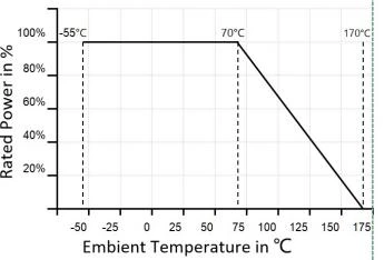
Derating Curve
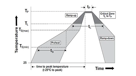
Recommended Solder Curve
| Reflow Condition | Pb - Free assembly | |
|---|---|---|
| Pre heat | -Temperature Min (Ts(min)) | 150℃ |
| -Temperature Min (Ts(min)) | 200℃ | |
| -Time (Min to Max)(ts) | 60 - 120 secs | |
| Average ramp up rate (Liqudus Temp(TL) to peak | 5℃/second max | |
| TS(max)to TL - Ramp-up Rate | 5℃/second max | |
| Reflow | -Temperature (TL) (Liquidus) | 217℃ |
| -Time(tL) | 60 - 150secs | |
| Peak Temperature (TP) | 260℃ | |
| Time within 5℃ of actual peak Temperature (tp) | 20 - 40seconds | |
| Ramp-down Rate | 5℃/second max | |
| Time 25℃ to peak Temperature (TP) | 8 minutes Max. | |
| Wave Soldering | 260℃, 10 seconds max. | |
| Hand Soldering | 350℃, 5 seconds max. | |
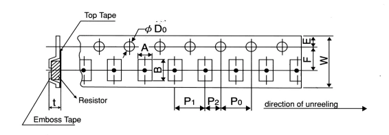
Tapping & Package
| Type | Pack | A ±0.2 |
B ±0.2 |
D0 0.05+/-0 |
E ±0.1 |
F ±0.05 |
P0 ±0.1 |
P1 ±0.1 |
P2 ±0.1 |
W ±0.2 |
T ±0.15 |
|---|---|---|---|---|---|---|---|---|---|---|---|
| 1206 | Paper | 2.00 | 3.60 | 1.50 | 1.75 | 3.50 | 4.00 | 4.00 | 2.00 | 8.00 | 0.81 |
Reel Specification
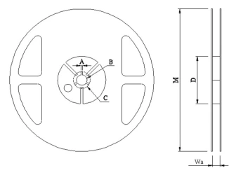
| Type | A | B | C | D | M | W |
|---|---|---|---|---|---|---|
| 1206 | 2.00±0.5 | 13.5±0.5 | 21.00±0.5 | 60.00±1.0 | 178.00±2.0 | 9.00±0.5 |
Packaging
Quantity: 5, 000pcs
8mm wide tape on 178mm(7 inch)
diameter reel -specification EIA Standard 481.