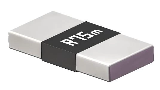
LMJ25 Current Sense Resistor
Description
- Thick copper material conductor
- High rated power
- Extremely low temperature drift(Good TCR)
- Ultra-long-term stability
- Metallic Material
- Halogen-free and lead-free compliant with RoHs
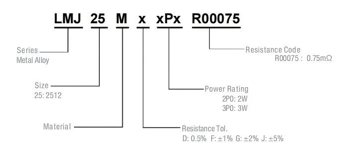
Part Numbering System
| Parameter | Standard |
|---|---|
| Power Rating | 2W&3W |
| Resistance Value | 0.75mQ |
| Operating Temperature Range | -55 to +170℃ |
| Component Temperature Coefficient(TCR) | ±100ppm/℃ |
| Maximum Working Voltage(V) | (PxR)1/2 |
| Rating Current(A) | (P/R)1/2 |
Standard Electrical Specifications
| Type | Rating Power at 70℃ |
T.C.R. (ppm/℃) |
Resistance Range(mQ) D:0.5%;F:1.0% G:2.0%;J:5.0% |
Meterial | Operating Temperature(℃) |
|---|---|---|---|---|---|
| LMJ25 | 2W&3W | ±100 | 0.75 | CuMn | -55~+170℃ |
Resistance Values of the 2512 Series, 2W Resistors
| Standard Resistance Values ( Ω ) | |||||||||
|---|---|---|---|---|---|---|---|---|---|
| 0ohm | 0.0005ohm | 0.001ohm | 0.002ohm | 0.003ohm | 0.004ohm | 0.005ohm | 0.006ohm | 0.008ohm | 0.01ohm |
| R000 | R0005 | R001 | R002 | R003 | R004 | R005 | R006 | R008 | R010 |
| Manufacturable Resistance Values ( Ω ) | ||||||||
|---|---|---|---|---|---|---|---|---|
| 0.00075ohm | 0.0012ohm | 0.0015ohm | 0.0025ohm | 0.0035ohm | 0.0038ohm | 0.0045ohm | 0.007ohm | 0.009ohm |
| R00075 | R0012 | R0015 | R0025 | R0035 | R0038 | R0045 | R007 | R009 |
Construction
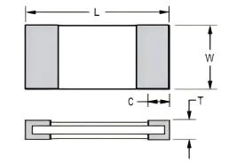
Unit: Millimeters
| Style | Resistance (mΩ) |
L | W | C | T |
|---|---|---|---|---|---|
| LMJ25 | 0.75 | 6.4 ± 0.2 | 3.2 ± 0.2 | 2.1 ± 0.25 | 0.9 ± 0.2 |
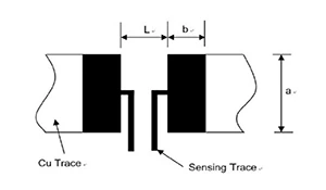
Recommended land pattern
Unit: Millimeters
|
Resistance
Range (mΩ )
|
a | b | L |
|---|---|---|---|
| 0.75 |
4.0±0.1
|
3.1±0.1
|
1.3±0.1
|
Derating Curve
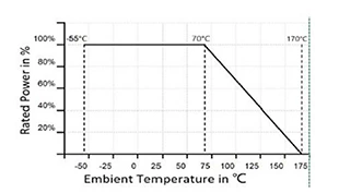 For resistors operated in ambient temperatures 70°C,
power rating shall be derated inaccording with the curve above:
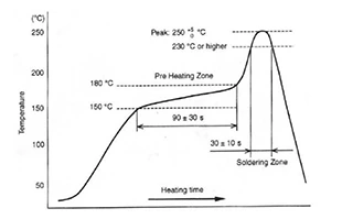
IR Reflow-Soldering Profile
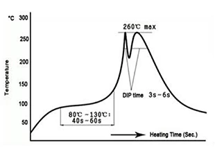
Wave- Soldering Profile
Product Characteristics
| Item | Test condition/Methods | Limited | Standard | ||
|---|---|---|---|---|---|
| Temperature coefficient of resistance |
TCR=(R-R0)/R0(T2-T1)X 10⁶ R0: resistance of room temperature R: resistance of 125℃ T1: Room temperature T2: Temperature at 125℃ |
Refer to Spec | MIL-STD-202 Method 304 |
||
| Short time Overload | Apply an overload for 5 seconds, then let it stand still for 24 hours before measuring the rate of change in resistance. |
≤±0.5% | JIS-C5201-1 4.13 | ||
| Type | Power (W) | # of rated power | |||
| 2512 | 3 | 5 times | |||
| Resistance to Soldering Heat |
260℃±5℃ time: 10sec± 1sec | ≤±0.5% | MIL-STD-202 Method 210 |
||
| Temperature Cycling | -55℃ (15min)/+150℃(15min), 1000 cycles | ≤±0.5% | MIL-STD-202 Method107G |
||
| Low temperature Storage |
-55±2℃ for 96 hours,No power | ≤±0.5% | MIL-STD-26E | ||
| High Temperature Storage |
170℃ for 1000hours, No power | ≤±1% | IEC6011501-4.25 | ||
| Bias Humidity | +85℃, 85%RH, 10%bias, 1000hours | ≤±0.5% | MIL-STD-202 Method103 |
||
| Solderability | 245±5℃, 3±1sec | At least 95%of surface area of electrode shall be covered with new solder |
IEC60115-1-4.17 JIS-C5201-4.17 |
||
| Load life | 70℃±2℃, 1000 hours, at rated power 1.5 hours “ON”, 0.5 hours “OFF” |
≤±1% | MIL-STD-202 Method 108 |
||
| Terminal Strength | (Flexural test) Weld it into the bending test plate, place it on the bending test machine, apply 2.5kg force in the center of the test plate, press 2mm under the load for 60s, and measure the resistance change rate. | ≤±0.5% | JIS-C5201-14.32 | ||
Tapping & Package
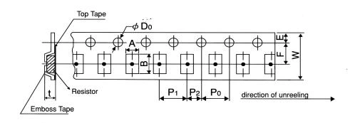
Unit: mm
| Type | Pack | A ±0.2 |
B ±0.2 |
D0 +0.05/-0 |
E ±0.1 |
F ±0.05 |
P0 ±0.1 |
P1 ±0.1 |
P2 ±0.1 |
W ±0.05 |
T ±0.15 |
|---|---|---|---|---|---|---|---|---|---|---|---|
| 2512 | Paper | 3.6 | 6.9 | 1.5 | 1.75 | 5.5 | 4 | 4 | 2 | 12 | 1.2 |
Reel Specification
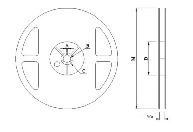
Unit: Millimeters
| Type | A | B | C | D | M | W |
|---|---|---|---|---|---|---|
| 2512 | 2.00±0.5 | 13.50±0.5 | 21.00±0.5 | 60.00±1.0 | 178.00±2.0 | 13.80±0.5 |
Packaging
Quantity: 4, 000pcs
8mm wide tape on 178mm(7 inch)
diameter reel -specification EIA Standard 481.