PMS45 Current Sense Resistor
Features
- Molded high temperature encapsulation.
- Improved thermal management incorporated into design.
- All welded construction of the Power Metal Strip resistors are ideal for all types of current sensing, voltage division and pulse applications.
- Sulfur resistance by construction that is unaffected by high sulfur environments.
- Solid metal nickel-chrome or manganese- copper alloy resistive element with low TCR (< 20 ppm/°C)
- Very low inductance 0.5 nH to 10 nH.
- Low thermal EMF (< 5 μV/°C)
- AEC-Q200 qualified available.
Part number
【1】Series Name: Power Metal Strip Resistors.
【2】Chip Size: 45: 4527.
【3】 Resistance Precision: F: ±1%.
【4】 Power Rating: 5P0: 5W.
【5】 Resistance Code: R080:80mΩ , R120:120mΩ , 8M20:8.2mΩ .
Electrical Characteristics
| Size | Power Rating at 70℃(W) |
Resistance Range (mΩ)* ±1% |
Element TCR ( ppm/℃) |
Operation Temperature Range |
Product temperature coefficient (ppm/℃) |
Insulation resistance |
|---|---|---|---|---|---|---|
| 4527 | 5 | 5~120 | <20 | -55℃~+170℃ | ±75:10mΩ≤R≤120mΩ ±110 :5mΩ≤R<10mΩ | >109 |
“*” : Other values may be available, contact factory
Resistance Values of the 4527 Series, 5W Resistors
| Standard Resistance Values(Ω) | ||||||
|---|---|---|---|---|---|---|
| 0.005ohm | 0.01ohm | 0.015ohm | 0.02ohm | 0.03ohm | 0.05ohm | 0.1ohm |
| R005 | R010 | R015 | R020 | R030 | R050 | R100 |
| Manufacturable Resistance Values ( Ω ) | ||||
|---|---|---|---|---|
| 0.0082ohm | 0.025ohm | 0.06ohm | 0.08ohm | 0.12ohm |
| R0082 | R025 | R060 | R080 | R120 |
Note:
1) Ir =(P/R)1/2 R: Resistance Value Ir: Rating Current P: Rating Power;
2) Product temperature coefficient: Includes the TCR effects of the resistor element and the copper terminal.
Physical Dimensions
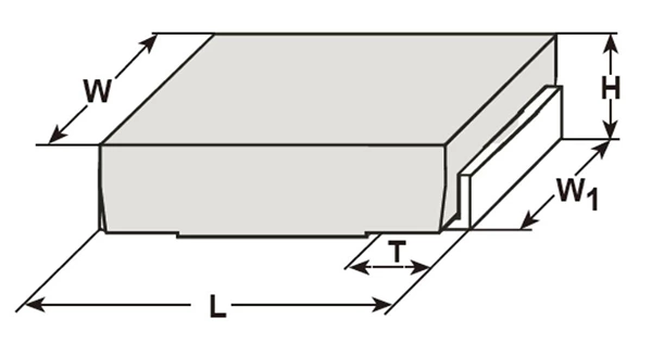
Unit: mm
| Type | Resistance (mΩ) | L | H | T | W | W1 |
|---|---|---|---|---|---|---|
| PMS45 | 5~120 | 11.60±0.60 | 2.50±0.30 | 2.80±0.50 | 7.00±0.3 | 5.46±0.20 |
Recommended Solder Pad Layout
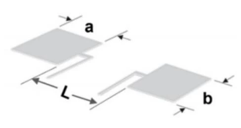
Unit: mm
| Type | a | b | c | I |
|---|---|---|---|---|
| PMS45 | 3.94 | 5.84 | 0.51 | 5.21 |
Marking Instructions
PMS45 is marked with four digit, We have two different ways of marking:
a. “ R ” designates the decimal location in ohms,
e. g. 80mΩ: R080; 120mΩ: R120
b. “m” designates the decimal location in milliohms,
e. g. 8.2mΩ: 8m20
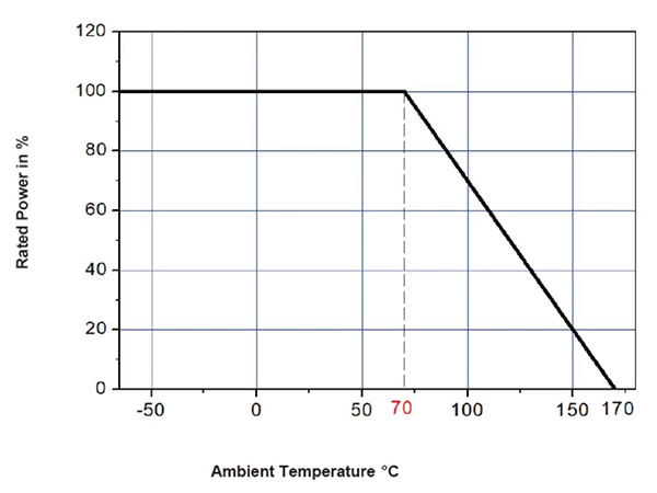
Power Derating Curve
For resistors operated in ambient temperatures 70°C, power rating shall be derated in according with the curve below:
Recommended Solder Curve
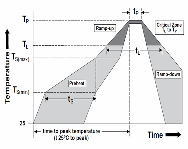
| Reflow Condition | Pb - Free assembly | |
|---|---|---|
| Pre heat | - Temperature Min (Ts(min)) | 150°C |
| - Temperature Max (Ts(max)) | 200°C | |
| - Time (Minto Max) (ts) | 60-120secs | |
| Average ramp up rate (Liquidus Temp (TL)to peak | 5°C/second max | |
| TS(max) to TL - Ramp-up Rate | 5°C/second max | |
| Reflow | - Temperature (TL) (Liquidus) | 217°C |
| - Time (tL) | 60 - 150 seconds | |
| Peak Temperature (TP) | 260°C | |
| Time within 5°C of actual peakTemperature (tp) | 20 - 40 seconds | |
| Ramp-down Rate | 5°C/second max | |
| Time 25°C to peak Temperature (TP) | 8 minutes Max. | |
| Wave Soldering | 260°C, 10 seconds max. | |
| Hand Soldering | 350°C, 5 seconds max. | |
Product Characteristics
| Item | Test condition/ Methods | Limited | Standard |
|---|---|---|---|
| Resistance | Measuring resistance value at room temperature 25℃±5℃ |
Refer to Spec | IEC60115-1 4.5 |
| External Visual | There is no need for electrical test, check the device structure, identification and process quality, and electrical test is not required. |
Refer to Spec | MIL-STD-883 Method 2009 |
| Physical Dimension | Verify physical dimensions according to device specifications. |
Refer to Spec | JESD22-B100 |
| Temperature Coefficient of Resistance | TCR (ppm/°C) = (R2-R1/R1*(T2-T1))X106 R1 : resistance value measured at room temperature (mΩ) R2 :Resistance measured at 125 °C (mΩ) T1 : room temperature (°C)| T2 : 125°C |
Refer to Spec | IEC 60115-1 4.8 |
| Short Time Overload | Apply 3 times rated power for 5 seconds, and measure the resistance change after standing for 24 hours. |
≤±2% | IEC 60115-1 4.13 |
| High Temperature Storage | 170℃ for 1000hours, No power. | ≤±1% | MIL-STD-202 Method 108 |
| Temperature Cycling | Pre-treatments with 3X reflow ,-55℃ (15min)/+150℃ (15min), 1000 cycles, transition time less than 1 minute |
≤±0.5% | JESD22-A104 |
| Bias Humidity |
Pre-treatments with 3X reflow ,+85 ℃, 85% RH ,
10% of operating power, 1000hours |
≤±0.5% | MIL-STD-202 Method103 |
| Operational life | Pre-treatments with 3X reflow ,70℃±2℃, 1000 hours, at rated power 1.5 hours “ON”, 0.5 hours “OFF” . |
≤±2% | MIL-STD-202 Method 108 |
| Mechanical shock | Condition C ,100 g’s ,6 msec, 3 mutually perpendicular axes, in 6 directions, three impacts each for a total of 18 times 18 shocks. |
≤±0.5% | MIL-STD-202 Method 213 |
| Vibration | 5g's for 20 minutes 12 cycles each of 3 orientations. Test from 10 Hz - 2000 Hz |
≤±0.5% | MIL-STD-202 Method 204 |
| Resistance to Soldering Heat | Condition K, temperature above 217°C, 60s – 150s | ≤±0.5% | MIL-STD-202 Method 210 |
| Solderability | 245±5℃ time: 5sec+0/-0.5sec. | ≥95% | J-STD-002 |
Packaging
Tape Dimensions
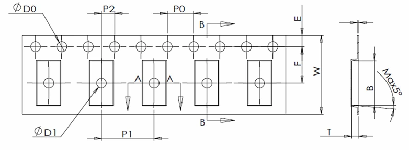
Unit: mm
| Series | Type | A | B | D0 | E | F | φD1 |
|---|---|---|---|---|---|---|---|
| 4527 | 5-120mΩ | 7.28±0.10 | 11.86±0.10 | 1.50±0.10 | 1.75±0.10 | 11.50±0.10 | 1.50±0.10 |
| Series | Type | W | P0 | P1 | P2 | T | |
| 4527 | 5-120mΩ | 24.0±0.30 | 4.00±0.10 | 12.0±0.10 | 2.00±0.10 | 2.71±0.10 |
Reel Dimensions
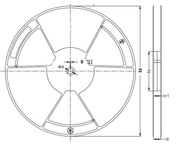
Unit: mm
| Series | Type | W (mm) |
M (mm) |
ΦA (mm) |
N (mm) |
H1 (mm) |
H2 (mm) |
|---|---|---|---|---|---|---|---|
| 4527 | 13’ reel | 24.4±1.0 | 330.0±2.0 | 13.4±0.5 | 100.0±0.2 | 24.4±1.0 | 28.6±1.0 |
Quantity of Package
| Type | Quantity (pcs) |
|---|---|
| 4527 | 1500 |
Storage
1. The temperature condition must be controlled at 25±5℃, The R.H. must be controlled at 60±15% Store in accordance with this requirement, and the validity period is two years after the date of manufacture.
2. Please avoid the mentioned harsh environment below when storing to ensure product performance and its’ weldability. Places exposed to sea breeze or other corrosive gas, such as Cl2 , H2S, NH3 , SO2 and NO2 .
3. When the product is moved and stored, please ensure the correct orientation of the box. Do not drop or squeeze the box. Otherwise, the electrode or the body of the product may be damaged.