PSRP59 Shunt Resistor
Features
- Metal Alloy Low-Resistance shunt resistor.
- Resistance value 0. 1mΩ , 0.2mΩ , 0.3mΩ , 0.5mΩ , 1mΩ , 1.5mΩ , 2mΩ , 3mΩ , 4mΩ , 5mΩ .
- Low thermal EMF.
- Low TCR.
- Very low inductance.
- Halogen free, lead free and RoHS compliant.
- AEC-Q200 qualified available.
Applications
- Power modules.
- Frequency converters.
- Current sensor for power hybrid sources high current for automotive.
- Lithium battery protection board.
Part Number
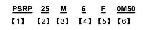
【1】Series Name:Prosemi Shunt Resistor for High Power Applications.
【2】Chip Size: 25: 2512,39:3921,59: 5930
【3】Material:M: CuMn,K:NiCr, F:FeCr, S:CuMnSn.
【4】Power Rating:15=15W,10=10W, 6=6W, 4=4W.
【5】Resistance Precision:D: ±0.5%,F: ±1%, G: ±2%,J: ±5%.
【6】Resistance Code:R002: 2mΩ, 0M50: 0.5mΩ,1M50:1.5mΩ.
Electrical Characteristics
| Size | Power Rating at 70℃* (W) |
Resistance Range (mΩ)** ±0.5%; ±1%; ±2%; ±5% |
Element Material |
Operation Temperature Range |
Temperature Coefficient (ppm/℃) |
|---|---|---|---|---|---|
| 2512 | 6 | 0.3 | M | -55℃ ~ +170℃ | ±175 |
| 6 | 0.5 | M | ±115 | ||
| 6 | 1 | M | ±100 | ||
| 6 | 2 | K | ±75 | ||
| 4 | 3 | K | ±75 | ||
| 4 | 4 | K | ±75 | ||
| 3 | 5 | K | ±75 | ||
| 3921 | 12 | 0.2 | M | ±200 | |
| 10 | 0.3 | M | ±150 | ||
| 9 | 0.4 | M | ±150 | ||
| 9 | 0.5 | M | ±75 | ||
| 9 | 0.7 | M | ±75 | ||
| 9 | 1 | M | ±75 | ||
| 7 | 2 | K | ±60 | ||
| 5 | 3 | K | ±60 | ||
| F | ±30 | ||||
| 5 | 4 | K | ±50 | ||
| 4 | 5 | K | ±50 | ||
| 5930 | 15 | 0.1 | S | ±200 | |
| 15 | 0.2 | M | ±100 | ||
| 10 | 0.3 | M | ±100 | ||
| 10 | 0.4 | M | ±100 | ||
| 10 | 0.5 | M | ±75 | ||
| 9 | 1 | K | ±50 | ||
| F | ±30 | ||||
| 8 | 1.5 | K | ±50 | ||
| 7 | 2 | K | ±50 | ||
| 7 | 3 | K | ±50 | ||
| 7 | 4 | K | ±50 |
“*” : Power at terminal temperature of 70℃ .
“* *”: Development schedule will vary depending on resistance value. Please contact us for resistance values.
Resistance Values of the 5930 Series, 8~12W Resistors
| Standard Resistance Values ( Ω ) | ||||||
|---|---|---|---|---|---|---|
| 0.0001ohm | 0.0002ohm | 0.0003ohm | 0.0005ohm | 0.0015ohm | 0.001ohm | 0.002ohm |
| 0M10 | 0M20 | 0M30 | 0M50 | 1M50 | R001 | R002 |
| Manufacturable Resistance Values ( Ω ) | |
|---|---|
| 0.003ohm | 0.004ohm |
| R003 | R004 |
Physical Dimensions
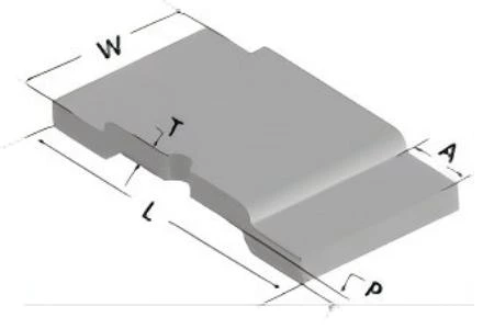
| Size | Resistance (mΩ) |
L | W | T | A | P | Element Material |
|---|---|---|---|---|---|---|---|
| 2512 | 0.3 | 6.4±0.2 | 3.2±0.2 | 0.95±0.1 | 1.53±0.3 | 0.4±0.1 | M |
| 0.5 | 0.7±0.1 | M | |||||
| 1 | 0.35±0.1 | M | |||||
| 2 | 0.5±0.1 | K | |||||
| 3 | 0.3±0.1 | K | |||||
| 4 | 0.25±0.1 | K | |||||
| 5 | 0.25±0.1 | K | |||||
| 3921 | 0.2 | 10±0.2 | 5.2±0.2 | 1.65±0.1 | 1.9±0.3 | 0.5±0.1 | M |
| 0.3 | 1.42±0.1 | M | |||||
| 0.4 | 1.42±0.1 | M | |||||
| 0.5 | 0.8±0.1 | M | |||||
| 0.7 | 0.6±0.1 | M | |||||
| 1 | 0.4±0.1 | M | |||||
| 2 | 0.6±0.1 | K | |||||
| 3 | 0.4±0.1 | K/F | |||||
| 4 | 0.3±0.1 | K | |||||
| 5 | 0.3±0.1 | K | |||||
| 5930 | 0.1 | 15±0.3 | 7.6±0.4 | 2.0±0.1 | 4.2±0.3 | 0.5±0.1 | S |
| 0.2 | 1.5±0.1 | M | |||||
| 0.3 | 1.0±0.1 | M | |||||
| 0.4 | 1.0±0.2 | M | |||||
| 0.5 | 0.6±0.1 | M | |||||
| 1 | 0.91±0.1 | K/F | |||||
| 1.5 | 0.60±0.1 | K | |||||
| 2 | 0.45±0.1 | K | |||||
| 3 | 0.3±0.1 | K | |||||
| 4 | 0.23±0.1 | K |
Recommended Solder Pad Layout
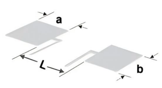
Unit: mm
| Type | Resistance(mΩ) | L | a | b |
|---|---|---|---|---|
| 2512 | 0.3~5 | 3.0 | 2.3 | 3.5 |
| 3921 | 0.2~5 | 5.6 | 2.7 | 6.2 |
| 5930 | 0.1~4 | 5.6 | 5.2 | 8.75 |
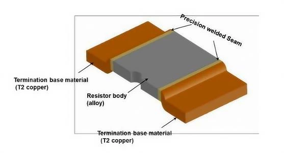
Construction
Power Derating Curve
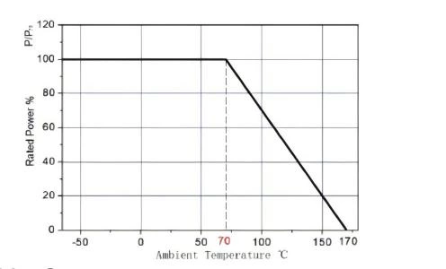
For resistors operated in ambient temperatures 70°C, power rating shall be derated in according with the curve above.
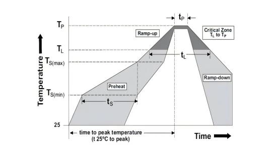
Recommended Solder Curve
| Reflow Condition | Pb – Free assembly | |
|---|---|---|
| Pre heat | - Temperature Min (Ts(min)) | 150°C |
| - Temperature Max (Ts(max)) | 200°C | |
| - Time (Min to Max) (ts) | 60 – 120 secs | |
| Average ramp up rate (Liquidus Temp (TL) to peak) | 5°C/second max | |
| TS(max) to TL - Ramp-up Rate | 5°C/second max | |
| Reflow | - Temperature (TL) (Liquidus) | 217°C |
| - Time (tL) | 60 – 150 seconds | |
| Peak Temperature (TP) | 260°C | |
| Time within 5°C of actual peak Temperature (tp) | 20 – 40 seconds | |
| Ramp-down Rate | 5°C/second max | |
| Time 25°C to peak Temperature (TP) | 8 minutes Max. | |
| Wave Soldering | Not applicable | |
| Hand Soldering | 350°C, 5 seconds max. | |
Product Characteristics
| Item | Test condition/ Methods | Limited | Standard |
|---|---|---|---|
| Resistance | Measuring resistance value at room temperature 25℃±5℃ | Refer to Spec | IEC60115-1 4.5 |
| Temperature Coefficient of Resistance | TCR (ppm/°C) = (R2-R1/R1*(T2-T1))×106 R1: resistance value measured at room temperature (Ω ) R2: Resistance measured at 125 °C (Ω) T1: room temperature (°C) T2: 125 °C |
Refer to Spec | IEC 60115-1 4.8 |
| Short Time Overload | Apply 5 times (3 times for 3921-5mΩ) rated power for 5 seconds, and measure the resistance change after standing for 24 hours. | ≤±0.5% | IEC 60115-1 4.13 |
| High Temperature Storage | 170℃ for 1000 hours, No power. | ≤±1% | MIL-STD-202 Method 108 |
| Temperature Cycling | -55 ℃(15min)/+150 ℃ (15min), 1000 cycles, transition time less than 1 minute | ≤±0.5% | JESD22-A104 |
| Bias Humidity | +85℃, 85% RH, 10% of operating power, 1000hours | ≤±0.5% | MIL-STD-202 Method103 |
| Operational life | 70℃±2℃, 1000 hours, at rated power 1.5 hours “ON”, 0.5 hours “OFF”. | ≤±1% | MIL-STD-202 Method 108 |
| Mechanical shock | Condition C, 100 g’s, 6 msec, 3 mutually perpendicular axes, in 6 directions, three impacts each for a total of 18 shocks. | ≤±0.5% | MIL-STD-202 Method 213 |
| Vibration | 5g's for 20 minutes 12 cycles each of 3 orientations. Test from 10 Hz - 2000 Hz |
≤±0.5% | MIL-STD-202 Method 204 |
| Resistance to Soldering Heat | Condition K, temperature above 217°C, 60s – 150s | ≤±0.5% | MIL-STD-202 Method 210 |
| Solderability | 245±5℃ time: 5sec+0/-0.5sec. | ≥95% | J-STD-002 |
Packaging
Tape Dimensions
Unit: mm
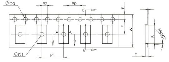
2512, 3921
| Series | Type | A | B | D0 | E | F | φD1 |
|---|---|---|---|---|---|---|---|
| 2512 | 0.3mΩ | 3.60±0.10 | 6.70±0.10 | 1.50+0.10 | 1.75±0.10 | 5.50±0.05 | 1.50±0.10 |
| 0.5-5mΩ | 3.50±0.10 | 6.74±0.10 | 1.50+0.10 | 1.75±0.10 | 5.50±0.05 | 1.50±0.10 | |
| 3921 | 0.2~0.4mΩ | 5.70±0.10 | 10.50±0.10 | 1.50+0.10/0 | 1.75±0.10 | 7.50±0.1 | / |
| 0.5-5mΩ | 5.50±0.10 | 10.50±0.10 | 1.50+0.10/0 | 1.75±0.10 | 7.50±0.1 | 1.50+0.10/0 | |
| 5930 | 0.1-4mΩ | 8.60±0.10 | 16.00±0.10 | 1.50+0.10/0 | 1.75±0.10 | 11.50±0.1 | / |
Unit: mm
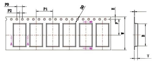
5930
| Series | Type | W | P0 | P1 | P2 | T |
|---|---|---|---|---|---|---|
| 2512 | 0.3mΩ | 12.00±0.30 | 4.00±0.10 | 8.00±0.10 | 2.00±0.05 | 2.10±0.10 |
| 0.5-5mΩ | 12.00±0.30 | 4.00±0.10 | 8.00±0.10 | 2.00±0.05 | 1.10±0.10 | |
| 3921 | 0.2~0.4mΩ | 16.00±0.30 | 4.00±0.10 | 8.00±0.10 | 2.00±0.10 | 2.25±0.10 |
| 0.5-5mΩ | 16.00±0.30 | 4.00±0.10 | 8.00±0.10 | 2.00±0.10 | 1.50±0.10 | |
| 5930 | 0.1-4mΩ | 24.00±0.30 | 4.00±0.10 | 12.00±0.10 | 2.00±0.10 | 2.75±0.10 |
Reel Dimensions
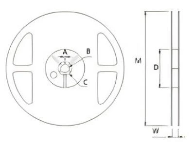
2512
Unit: mm
| Series | Type | W (mm) |
M (mm) |
A (mm) |
B (mm) |
C (mm) |
D (mm) |
|---|---|---|---|---|---|---|---|
| 2512 | 7’ reel | 13.8±0.5 | 178.0±2.0 | 2.0±0.5 | 13.5±0.5 | 21.0±0.5 | 80.0±1.0 |
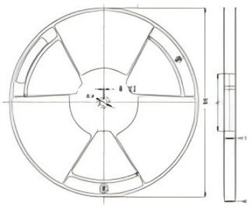
3921, 5930
Unit: mm
| Series | Type | W (mm) |
M (mm) |
ΦA (mm) |
N (mm) |
H1 (mm) |
B (mm) |
|---|---|---|---|---|---|---|---|
| 3921 | 13’ reel | 16.4+3.5/-0.2 | 330.0±2.0 | 13.4±0.5 | 100.0±0.2 | 16.4±1.0 | 2.4±0.4 |
| 5930 | 13’ reel | 24.4+3.5/-0.2 | 330.0±2.0 | 13.4±0.5 | 100.0±0.2 | 24.4±1.0 | 2.4±0.4 |
Quantity of Package
| Type | Quantity(pcs) |
|---|---|
| 2512 | 0.3mΩ:1000 0.5-5mΩ:2000 |
| 3921 | 0.2~0.4mΩ:2000 0.5-5mΩ:2500 |
| 5930 | 0.1-0.2mΩ:1000 0.3-4mΩ:2000 |
Storage
1.The temperature condition must be controlled at 25 ±5℃ , The R.H. must be controlled at 60±15% Store in accordance with this requirement, and the validity period is two years after the date of manufacture.
2.Please avoid the mentioned harsh environment below when storing to ensure product performance and its’ solderability. Places exposed to sea breeze or other corrosive gas, such as Cl2 , H2S, NH3 , SO2 and NO2.
3.When the product is moved and stored, please ensure the correct orientation of the box. Do not drop or squeeze the box. Otherwise, the electrode or the body of the product may be damaged.