MSR12 Alloy Samping Resistor
Description
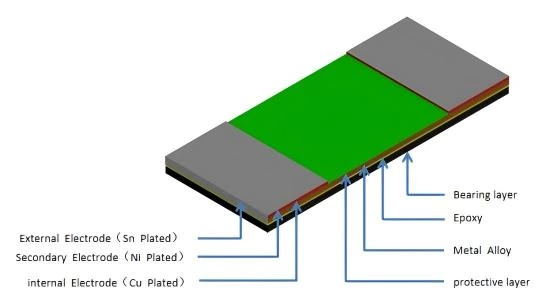
- Metal Alloy Short Terminal Low-Resistance Resistor
- Low thermal EMF
- Low TCR
- Low inductance
Applications
- Battery pack
- Inverter/Converter
- Consumer electronics
- Laptops
Part number
【1】Series Name: Metal alloy Short terminal Resistor
【2】Chip Size: 06:0603, 08:0805, 12: 1206
【3】Terminals: A:2 terminals , B:4 terminals
【4】 Power Rating: E=0.5W, D=0.75W, 1=1W
【5】 Resistance Code: R002: 2mΩ , 1M50: 1.5mΩ
【6】 Resistance Precision: D:±0.5%, F:±1%, G:±2%, J: ±5%
【7】 Internal Code
Electrical Characteristics
| Part number | Power Rating at 70℃(W) |
Resistance Range (mΩ) |
TCR (ppm/℃) |
Resistance Tolerance (%) |
Rating Current |
Operation Temperature Range |
|---|---|---|---|---|---|---|
| MSR12A1R001F2 | 1 | 1 | ±100 | ±0.5; ±1.0 | (P/R)1/2 | -55℃ ~+150℃ |
| MSR12A11M50~R004F2 | 1.5~4 | ±75 | ||||
| MSR12A1R005~R020F2 | 5~20 | ±50 | ||||
| MSR08ADR001F2 | 0.75 | 1 | ±200 | |||
| MSR08AD1M50~R002F2 | 1.5~2 | ±100 | ||||
| MSR08ADR003~R005F2 | 3~5 | ±75 | ||||
| MSR08ADR006~R020F2 | 6~20 | ±50 | ||||
| MSR06AER002~R003F1 | 0.5 | 2~3 | ±150 | |||
| MSR06AER004~R005F1 | 4~5 | ±100 | ||||
| MSR06AER006~R010F1 | 6~10 | ±75 |
Note: P=Rating Power ; R=Resistance Value
Resistance Values of the 1206 Package, 1W Resistors
| Standard Resistance Values ( Ω ) | ||||||||
|---|---|---|---|---|---|---|---|---|
| 0.002ohm | 0.003ohm | 0.004ohm | 0.005ohm | 0.008ohm | 0.009ohm | 0.01ohm | 0.015ohm | 0.02ohm |
| R002 | R003 | R004 | R005 | R008 | R009 | R010 | R015 | R020 |
| Manufacturable Resistance Values ( Ω ) | |||||
|---|---|---|---|---|---|
| 0.0015ohm | 0.001ohm | 0.006ohm | 0.007ohm | 0.015ohm | 0.02ohm |
| 1M50 | R001 | R006 | R007 | R015 | R020 |
Physical Dimensions
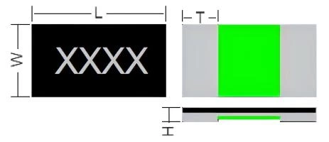
Fig.1
Unit: mm
| Part number | L | W | H | T |
|---|---|---|---|---|
| MSR12A1R001F2 | 3.20±0.25 | 1.60±0.25 | 0.45±0.10 | 1.15±0.20 |
| MSR12A11M50~R002F2 | 3.20±0.25 | 1.60±0.25 | 0.45±0.10 | 0.95±0.20 |
| MSR12A1R003F2 | 3.20±0.20 | 1.60±0.20 | Max 0.45 | 0.85±0.15 |
| MSR12A1R004~R005F2 | 3.20±0.20 | 1.60±0.20 | Max 0.40 | 0.85±0.15 |
| MSR12A1R006~R020F2 | 3.20±0.20 | 1.60±0.20 | Max 0.40 | 0.58±0.15 |

Fig.2
Unit: mm
| Part number | L | W | H | T |
|---|---|---|---|---|
| MSR08ADR001F2 | 2.06±0.25 | 1.26±0.25 | 0.40±0.10 | 0.63±0.20 |
| MSR08AD1M50~R002F2 | 2.06±0.25 | 1.26±0.25 | 0.40±0.10 | 0.48±0.20 |
| MSR08ADR003~R004F2 | 2.06±0.20 | 1.26±0.20 | Max 0.45 | 0.43±0.15 |
| MSR08ADR005~R020F2 | 2.06±0.20 | 1.26±0.20 | Max 0.40 | 0.43±0.15 |
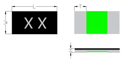
Fig.3
Unit: mm
| Part number | L | W | H | T |
|---|---|---|---|---|
| MSR06AER002F2 | 1.60±0.20 | 0.80±0.20 | 0.45±0.10 | 0.50±0.15 |
| MSR06AER003~R004F2 | 1.60±0.20 | 0.80±0.20 | 0.35±0.10 | 0.45±0.15 |
| MSR06AER005~R010F2 | 1.60±0.20 | 0.80±0.20 | 0.30±0.10 | 0.35±0.15 |
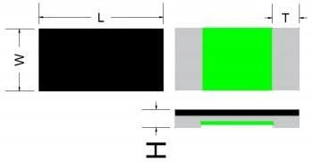
Unit: mm
| Part number | L | W | H | T |
|---|---|---|---|---|
| MSR06AER002F1 | 1.60±0.20 | 0.80±0.20 | 0.45±0.10 | 0.50±0.15 |
| MSR06AER003~R004F1 | 1.60±0.20 | 0.80±0.20 | 0.35±0.10 | 0.45±0.15 |
| MSR06AER005~R010F1 | 1.60±0.20 | 0.80±0.20 | 0.30±0.10 | 0.35±0.15 |
Marking Instructions
MSR12A is marked with four digit(Ref to Fig.1). We have two different ways of marking:
a. “ R” designates the decimal location in ohms
e.g. 2mΩ : R002; 10mΩ : R010;
b. “m” designates the decimal location in milliohms
e.g. 2.5mΩ : 2m50; 5.5mΩ : 5m50;
MSR08A is marked with three digit(Ref to Fig.2). We have two different ways of marking:
a. “ R” designates the decimal location in ohms
e.g. 2mΩ : 002; 10mΩ : 010
b. “m” designates the decimal location in milliohms
e.g. 2.5mΩ : 2m5; 5.5mΩ : 5m5 MSR06A no marking.
Construction
Recommended Solder Pad Layout
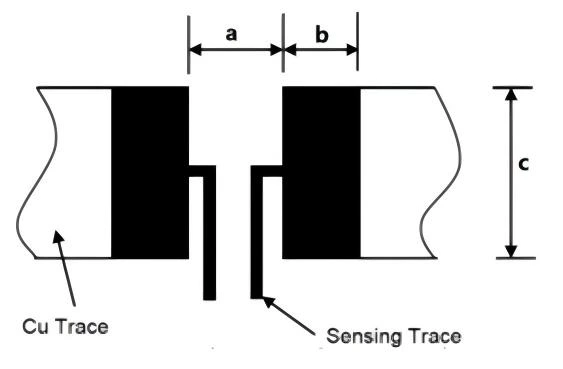
Unit: mm
| Part number | a | b | c |
|---|---|---|---|
| MSR12A1R001~R002F2 | 0.90 | 1.95 | 1.74 |
| MSR12A1R003~R005F2 | 1.00 | 1.85 | 1.74 |
| MSR12A1R006~R020F2 | 1.20 | 1.75 | 1.74 |
| Part number | a | b | c |
|---|---|---|---|
| MSR08ADR001~R020F2 | 0.80 | 1.45 | 1.40 |
| Part number | a | b | C |
|---|---|---|---|
| MSR06AER002F2 | 0.50 | 1.35 | 0.92 |
| MSR06AER003~R010F2 | 0.60 | 1.30 | 0.92 |
| MSR06AER002F1 | 0.50 | 1.35 | 0.92 |
| MSR06AER003~R010F1 | 0.60 | 1.30 | 0.92 |
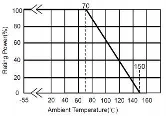
Power Derating Curve
For resistors operated in ambient temperatures 70°C, power rating shall be derated in according with the
curve below:
Recommended Solder Curve
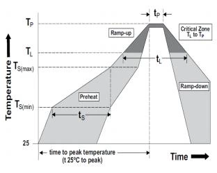
| Reflow Condition | Pb - Free assembly | |
|---|---|---|
| Pre heat | - Temperature Min (TS(min)) | 150°C |
| - Temperature Max (TS(max)) | 200°C | |
| - Time (Min to Max) (tS) | 60 - 120 secs | |
| Average ramp up rate (Liquidus Temp (TL) to peak | 5°C/second max | |
| TS(max) to TL - Ramp-up Rate | 5°C/second max | |
| Reflow | - Temperature (TL) (Liquidus) | 217°C |
| - Temperature (tL) | 60 - 150 seconds | |
| Peak Temperature (TP) | 260°C | |
| Time within 5°C of actual peak Temperature (tP) | 20 - 40 seconds | |
| Ramp-down Rate | 5°C/second max | |
| Time 25°C to peak Temperature (TP) | 8 minutes Max. | |
| Wave Soldering | Not applicable | |
| Hand Soldering | 350°C, 5 seconds max. | |
Product Characteristics
| Item | Test condition/ Methods | Limited | Standard | ||||
|---|---|---|---|---|---|---|---|
| Temperature coefficient of resistance |
TCR =(R-R0)/R0(T2-T1)X 106 R0 : resistance of room temperature R: resistance of 125℃ T1: Room temperature T2: Temperature at 125℃ |
Refer to Spec | MIL-STD-202 Method 304 |
||||
| Short time Overload | Applied Overload for 5 seconds , then measure its resistance variance rate. (Test condition refer to below): |
≤±1.0% | IEC60115-1 4.13 | ||||
| Type | Resistance(mΩ) | Rated power | |||||
| 1206 | 1≤R≤10 | 4 times | |||||
| 10<R≤20 | 3 times | ||||||
| 0805 | 1≤R≤10 | 4 times | |||||
| 10<R≤20 | 3 times | ||||||
| 0603 | 2≤R≤10 | 4 times | |||||
| Resistance to Soldering Heat |
260℃±5℃ time :12sec± 0.5sec | ≤±0.5% | MIL-STD-202 Method 210 |
||||
| Solderability | Temperature of Solder:245±5℃ Dipping time:3±0.5s |
Solder coverage over 95% |
IEC60115-1 4.17 | ||||
| Temperature Cycling | -55℃ (15min)/+150℃(15min), 300 cycles | ≤±1.0% | MIL-STD-202 Method107G |
||||
| Low temperature Storage |
-55℃ for 1000hours, No power | ≤±1.0% | IEC60115-1 4.23.4 | ||||
| High Temperature Storage |
150℃ for 1000hours, No power | ≤±1.0% | IEC60115-1 4.25 | ||||
| Bias Humidity | +85℃ , 85% RH ,10%bias, 1000hours | 1~10mR, △R≤±1% 1~20mR,△R≤±2% |
MIL-STD-202 Method103 |
||||
| Vibration | 5g's for 20 minutes 12 cycles each of 3 orientations. Test from 10 Hz - 2000 Hz |
≤±0.5% | MIL-STD-202 Method 204 |
||||
| Operational life |
70℃± 2℃, 1000 hours, at rated power 1.5
hours “ON”, 0.5 hours “OFF”
|
1206: 1~9mR , △R≤±1% 10~14mR, 15~20mR 0805: 1~10mR, △R≤±1% 11~20mR,△R≤±3% 0603: 2~10mR, △R≤±1% |
MIL-STD-202 Method 108 |
||||
| Moisture resistance |
MIL-STD-202,method106, No power, 7b not
required
|
≤±0.5% | MIL-STD-202 Method 106 |
||||
Note : Measurement at 24±4 hours after test conclusion for all reliability tests-parts.
Packaging
Tape Dimensions
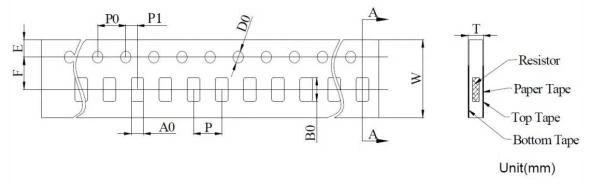
| Type | A0 | B0 | E | F | W |
|---|---|---|---|---|---|
| MSR12A | 2.00±0.20 | 3.60±0.20 | 1.75±0.10 | 3.50±0.05 | 8.00±0.20 |
| P0 | P | P1 | D0 | T | |
| 4.00±0.10 | 4.00±0.10 | 2.00±0.05 | 1.50±0.10 | 0.55±0.20 | |
| Type | A0 | B0 | E | F | W |
| MSR08A | 1.66±0.20 | 2.46±0.20 | 1.75±0.10 | 3.50±0.05 | 8.00±0.20 |
| P0 | P | P1 | D0 | T | |
| 4.00±0.10 | 4.00±0.10 | 2.00±0.05 | 1.50±0.10 | 0.55±0.20 | |
| Type | A0 | B0 | E | F | W |
| MSR06A | 1.00±0.20 | 1.80±0.20 | 1.75±0.10 | 3.50±0.05 | 8.00±0.20 |
| P0 | P | P1 | D0 | T | |
| 4.00±0.10 | 4.00±0.10 | 2.00±0.05 | 1.55±0.10 | 0.60±0.20 |
Reel Dimensions
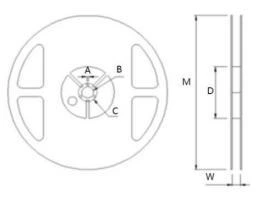
Unit: mm
| Type | M | W | A | B | C | D |
|---|---|---|---|---|---|---|
| 7 inch reel | 178.0±2.0 | 8.4+0.5/-0 | 2.0±0.5 | 13.2±0.5 | 17.70±0.5 | 60.0±1.0 |
Quantity of Package
| Type | MSR12A | MSR08A | MSR06A |
|---|---|---|---|
| Quantity(pcs) | 5000 | 5000 | 5000 |
Storage
The temperature condition must be controlled less than 40℃, The R.H. must be controlled less than 75%. Store in accordance with this requirement, and the validity period is two years after the date of manufacture.
Please avoid the mentioned harsh environment below when storing to ensure product performance and its’ weldability. Places exposed to sea breeze or other corrosive gas, such as Cl2 , H2S, NH3 , SO2 and NO2 .
When the product is moved and stored, please ensure the correct orientation of the box. Do not drop or squeeze the box. Otherwise, the electrode or the body of the product may be damaged.