1206TD-15AS
Time Delay | 0.126x0.064 inch
Thick Film Chip Fuses
1206TD Series are the fuses set the industry standard for performance, reliability and quality. The solder-free design provides excellent on-off and temperature cycling characteristics during use and also makes our SMD fuses more heat and shock tolerant than typical subminiature fuses.
Features
- High inrush current withstanding capability
- AEC-Q200 Automotive Grade Certified
- Compatible with reflow and wave solder
- Ceramic and glass construction
- Excellent environmental integrity
- One time positive disconnect
- Lead Free and Halogen free material
Appications
- Flat panel displays and televisions
- Automotive infotainment and ECU
- Computer servers
- Portable electronics
- Mobile device chargers
- Power Battery Packs
Electrical Characteristics
| Rated Current | 1.0 In | 2.5 In | 3.0 In | 3.5 In | 10 In |
|---|---|---|---|---|---|
| 4.5A ~ 5A | 4 hours min. | 5 sec max. | 0.1 sec – 3 sec | – | 0.2 ms – 20 ms |
| 6A ~ 40A | 4 hours min. | – | – | 5 sec max. | 0.2 ms – 20 ms |
Specifications
| Part Number | Ampere Rating (A) | Voltage / Interrupting Rating | Typical Cold Resistance (Ω) | Typical Melting I²t (A²Sec) | Typical Voltage Drop (V) | Marking Code |
|---|---|---|---|---|---|---|
| 1206TD-4.5AS | 4.50 | 72Vdc @ 50A 63Vdc @ 50A 32Vdc @ 50A |
0.027 | 2.65 | 0.164 | X |
| 1206TD-5AS | 5.00 | 0.022 | 4 | 0.145 | T | |
| 1206TD-6AS | 6.00 | 0.0145 | 12 | 0.140 | F | |
| 1206TD-7AS | 7.00 | 0.0105 | 14 | 0.130 | 7 | |
| 1206TD-8AS | 8.00 | 48Vdc @ 200A 36Vdc @ 200A 32Vdc @ 200A |
0.0070 | 16 | 0.123 | V |
| 1206TD-10AS | 10.0 | 0.0050 | 22 | 0.110 | U | |
| 1206TD-12AS | 12.0 | 0.0043 | 40 | 0.080 | W | |
| 1206TD-15AS | 15.0 | 0.0035 | 45 | 0.085 | Y | |
| 1206TD-20AS | 20.0 | 0.0022 | 50 | 0.080 | Q | |
| 1206TD-25AS | 25.0 | 0.00155 | 58 | 0.090 | L | |
| 1206TD-30AS | 30.0 | 0.00132 | 95 | 0.090 | Z | |
| 1206TD-40AS | 40.0 | 36Vdc @ 200A 32Vdc @ 200A |
0.00085 | 240 | 0.095 | XL |
- DC Interrupting Rating (Measured at rated voltage, time constant of less than 50 microseconds, battery source)
- DC Cold Resistance are measured at <10% of rated current in ambient temperature of 25℃
- Typical Pre-arcing I2 t are measured at 10In Current. Choice fuse for surge application (USB charger etc.), make sure the I2 t of fuse is 4 times than surge. Specifications are subject to change without notice. Application testing is strongly recommended
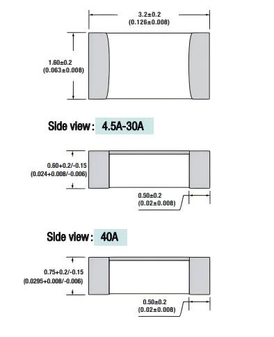
Dimension
Unit: mm/inch
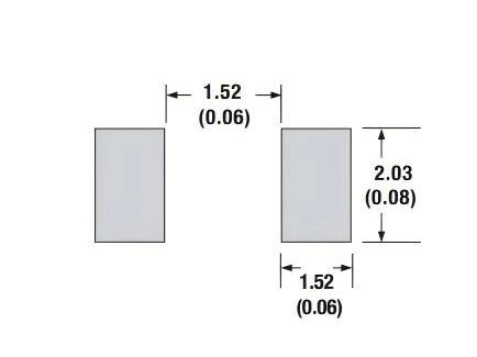
Pad layout
Packaging
- Quantity: 3 000pcs
- 8mm wide tape on 178mm(7 inch) diameter reel -specification EIA Standard 481.
Soldering Parameters
Wave Soldering: 260°C, 10 seconds max.
Infrared Reflow: 260°C, 30 seconds max.
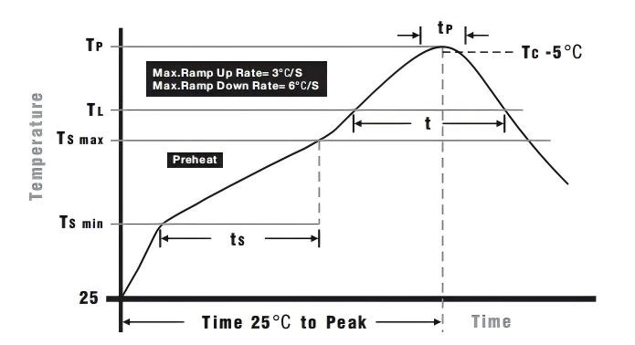
IR Reflow Profile
| Preheat Heat | |
|---|---|
| Temperature Min (Tsmin) | 150°C |
| Temperature Max (Tsmax) | 200°C |
| Time (Tsmin to Tsmax), ts | 60 – 120 seconds |
| Average Ramp-up Rate (Tsmax to Tp) | 3°C/second max. |
| Liquidous Temperature (TL) | 217°C |
| Time at Liquidous (tL) | 60 – 150 seconds |
| Peak Temperature (Tp) | 260 +0/-5°C |
| Time within 5°C of Peak (tp) | 10 – 30 seconds |
| Average Ramp-down Rate (Tp to Tsmax) | 6°C/second max. |
| Total Time (25°C to Peak) | 8 minutes max. |
Temperature Derating Curve
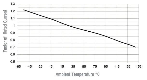
- Normal ambient temperature: 23+/-3℃
- Operating temperature: -55 ~ 150℃, with proper correction factor applied
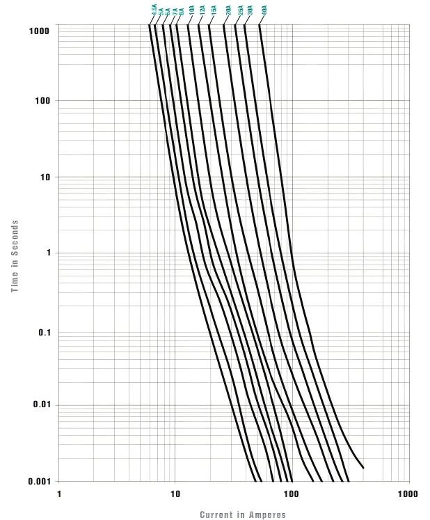
Average Time Current Curves