Complete Guide To Selection And Application Of Chip Fuses
introduction
With the continuous miniaturization and improvement of integration of electronic devices, circuit protection components must also take into account small size, stable performance and easy installation. Chip Fuse (surface mount fuse) has become an indispensable protective component in modern electronic systems due to its small size, rapid response and adaptability to automated mounting. This article will comprehensively introduce the types, characteristics, main parameters, selection ideas, installation precautions and typical applications of surface mount fuses.
What is Chip of uses?
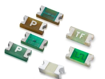
Chip Fuse is a surface mount device used for circuit protection. It rapidly melts when the current abnormally rises (such as short circuit or overload) to prevent damage to downstream components. It is usually composed of a ceramic or polymer material base and an internal metal fuse, and can be applied to large-scale automated SMT manufacturing processes.
The main advantages include:
Small size, suitable for high-density circuit boards;
Fast melting speed and timely protection response;
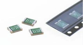
It is convenient for reflow soldering process and suitable for automatic mounting.
Types and Characteristics
Classified by response speed
| Type | Characteristic Description | Common Application Scenarios |
|---|---|---|
| Fast-acting | Responds quickly to sudden overcurrent; suitable for sensitive component protection | Power input, battery protection, etc. |
| Time-delay | Withstands short-term inrush current; prevents false tripping | Motor drives, power supplies with capacitive input |
| Ultra-fast | Extremely low melting energy; ideal for high-precision electronics | Communication modules, sensor front-ends |
Classified by package size

The packaging of Chip Fuses is directly related to its installation method, electrical performance, heat dissipation capacity and applicable scenarios. In actual selection and design, the package size should not only take into account electrical parameters, but also take into account the PCB spatial layout, compatibility of mounting processes and thermal management requirements.
| Package Code | Size (inches) | Size (mm) | Features & Application Scenarios |
|---|---|---|---|
| 0402 | 0.04 × 0.02 | 1.0 × 0.5 | Ultra-miniature package for extremely space-constrained, low-power devices such as smartphones, earbuds, and smartwatches. Rated currents typically from tens of mA up to 0.5 A; ideal for signal-line and sensor-power protection. |
| 0603 | 0.06 × 0.03 | 1.6 × 0.8 | Common SMD package used in small electronics like wearables and compact communication modules. Supports up to 1 A; suitable for basic I/O interfaces, LED circuits, etc. |
| 0805 | 0.08 × 0.05 | 2.0 × 1.25 | Balanced performance package widely used in consumer electronics, power modules, and low-power automotive applications. Can handle 3–4 A; offers good mechanical stability. |
| 1206 | 0.12 × 0.06 | 3.2 × 1.6 | Supports higher currents (typically 5–10 A). Used in routers, power input ports, lithium-battery protection boards, and other applications requiring greater interrupt capability. |
| 2010 / 2512 | 5.0 × 2.5 / 6.3 × 3.2 | 5.0 × 2.5 / 6.3 × 3.2 | Large-format packages for high-power or industrial use—e.g., power adapters, high-power LEDs, motor drivers. High current handling and thermal tolerance but occupy more PCB area. |
Application selection suggestions:
- Portable devices: Give priority to small-sized models such as 0402 and 0603 to meet the ultimate size constraints.
- For medium-power scenarios such as smart speakers, tablet computers, and communication modules, 0805 and 1206 can be selected to balance power and space.
- Industrial and automotive applications: It is recommended to use 1206, 2010 or larger packages to ensure stable heat dissipation and surge resistance.
Process precautions:
- The smaller the package, the more crucial the temperature control of reflow soldering is. It is recommended to perform precise temperature curve control below 0603.
- For large-sized packages such as 1206 and above, to ensure reliable soldering, it is necessary to use larger pads and good wiring to enhance heat dissipation.
- For equipment that requires manual maintenance, 0805/1206 is easier to disassemble, assemble and replace.
Classified by the rated current range
Less than 1A: Signal lines, battery detection circuits;
1 A - 10 A: USB, power module, LED light driver, etc.
Greater than 10A: High-power industrial equipment or vehicle-mounted modules.
Key performance parameters
When choosing surface mount fuses, the following parameters should be given particular attention: When purchasing Chip Fuses (surface mount fuses), understanding their key performance parameters is the basis for ensuring protection effects and circuit stability. The following will provide a detailed introduction to the definition, function and selection suggestions of each parameter.
Rated Current
- It refers to the maximum current value that a fuse can withstand for a long time without blowing in a standard temperature environment.
- When selecting the type, the normal operating current of the load should be taken into account. Generally, it is recommended to choose a fuse rating that is slightly 25% to 50% higher than the actual current.
- Example: If the maximum working current of a certain load is 0.8A, it is recommended to use a fuse with a rated current of 1.0A.
-
Note: The increase in temperature in the actual usage environment will reduce the load-bearing capacity of the fuse. Adjustments should be made in combination with the temperature derating curve.
Rated Voltage
- It indicates the maximum voltage value that the fuse can safely withstand when disconnected.
- If the circuit voltage exceeds this value, the fuse may not be able to effectively arc out and extinguish, posing a risk of breakdown or short circuit.
- Common voltage levels include: 24V, 32V, 63V, 125V, and 250V, which need to be matched with the actual circuit supply voltage.
Time-Current Characteristics
Describe the melting time of fuses under different overcurrent conditions. Common types include:
| Type | Feature Description | Recommended Applications |
|---|---|---|
| Fast-Acting | Responds to abnormal short-duration overcurrent in <1 ms | Precision analog circuits, IC front-end protection |
| Time-Delay | Tolerates short-term inrush currents; prevents nuisance tripping | Motor drives, power supplies with capacitive input |
| Very Fast | Even faster response; suitable for high-speed circuit protection | Communication systems, lightning protection modules |
Manufacturers generally provide the I²t value (fuse energy) and the time-current curve graph to match the load startup characteristics.
Breaking Capacity
- It indicates the maximum current value that the fuse can reliably cut off, and the common units are amperes (A) or kiloamperes (kA).
- For applications with a high risk of short-circuit current, such as power input ports and on-board power supply systems, the disconnection capability is particularly important.
Cold Resistance
- It indicates the resistance value of the fuse in the unblown state, usually at the milliohm (mΩ) level.
- For circuits that require high efficiency or low voltage drop, models with lower impedance should be selected.
-
Excessive impedance may lead to severe heating and excessive voltage drop, affecting the performance of the circuit.
Temperature Derating
- The load-bearing capacity of fuses decreases as the ambient temperature rises, and the temperature coefficients vary among different models.
- In high-temperature or closed environments, the derating curve provided by the manufacturer should be referred to for correction.
- For example, at 60°C, the rated current of a certain type of fuse might need to be reduced from 2A to 1.6A.
Size & Package
- The package size not only affects the installation space, but also determines the heat dissipation performance and current carrying capacity of the fuse.
- The larger the package, the higher the power and current it generally supports, but at the same time, it occupies more board area.
How to choose surface mount fuses?
Set the rated current according to the current demand of the protected circuit
- The initial selection basis is the normal working current multiplied by 1.2 to 1.5.
- If there is a surge in the circuit, the tolerance of the fuse should be considered.
Select the response speed according to the load type
- For precision circuits or sensitive components, it is recommended to choose the fast-melting type.
- For loads with relatively large starting currents, such as motors and switching power supplies, slow-melting types should be selected.
Confirm packaging compatibility
- It should be compatible with PCB layout and reflow soldering process;
- Pay attention to the issue of thermal interference with surrounding components.
Verify the usage environmental conditions
- When used in high-temperature or high-humidity environments, derating design should be considered.
- For applications with high reliability requirements, certified products (such as EC-Q200) should be given priority.
Installation and maintenance suggestions
- Mounting process: Standard reflow soldering curves should be adopted to avoid temperature overshoot damage to the fuse structure.
- Layout optimization: It is recommended to reserve heat dissipation space around the fuse or use copper foil to enhance heat dissipation.
- Circuit design: Add test points in areas with high failure rates to facilitate debugging and replacement.
- Fault analysis: After the circuit breaker blows, it is necessary to confirm whether the overcurrent is an abnormal phenomenon to prevent repeated circuit breakers.
- In addition, it is recommended to retain the replacement plan in the design, such as choosing an alternative model with a fuse holder for convenient maintenance.
Typical application cases
- Mobile phones and tablets: Used for battery management systems and overcurrent protection of power input ports;
- Industrial control board: PLC, power module, interface protection;
- Communication equipment: RF circuit protection in base stations and routers;
- Automotive electronics: ADAS cameras, T-BOX power protection, etc.
- In these scenarios, surface mount fuses not only provide protection but also enhance the reliability and safety of the system's long-term operation.
Frequently Asked Questions
Q: Is it safer to choose a fuse with a larger current value?
A: Don't blindly choose a larger one; otherwise, it won't be able to fuse in time under abnormal circumstances, which may cause the device to burn out.
Q: Can fuses be reused?
A: It cannot be reused. Once it melts, a new one needs to be replaced.
Q: What are the differences between surface mount fuses and PPTC?
A: The former features one-time circuit breaker and fast response, making it suitable for critical protection scenarios. The latter can reset automatically and is suitable for non-critical and low-cost applications.
conclusion
Chip Fuses is an efficient and reliable overcurrent protection solution in modern electronic products. By rationally choosing the type, precisely matching the current level and packaging method, the design size and cost can be optimized while ensuring the safety of the circuit.
It is recommended that fuses be included in the protection scheme planning in the early stage of product design, and selection verification be carried out in combination with measured data to enhance the overall stability and risk resistance capacity of the system.
For more information on model parameters, to obtain samples or for technical support, please feel free to contact us for in-depth consultation.