How To Choose The Right Shunt Resistor For Your Circuit
Choosing the right shunt resistor is essential for accurate current measurement, stable performance, and long-term reliability. A poor selection can lead to excessive heat, inaccurate readings, or even circuit failure.
This guide breaks down everything you need to know — from resistance calculation to thermal design and PCB layout.
Ask Three Questions Before You Start
What is your current range? (I_max, I_nom) — determines resistance value and power rating.
What accuracy do you need? (±0.1%, ±0.5%, or just approximate) — defines tolerance and TCR requirements.
What’s your environment? (temperature range, vibration, space, high-side or low-side measurement).
Key Formulas
Resistance:
Power Dissipation:
Temperature Drift (approximation):
Target Sensing Voltage (V_sense)
Typical range: 10–100 mV
- Too low (<10 mV): requires high-gain amplifiers and increases offset errors.
- Too high (>100–200 mV): increases power loss and self-heating.
Rule of thumb:
Use 10–100 mV for high-current circuits (tens or hundreds of amps),
and tens to hundreds of mV for low-current applications.
Example Calculations
Example A: Measuring 100 A, target V_sense = 50 mV
R=0.05/100=0.0005 Ω=500 μ
P=1002×0.0005=5 W
Choose a resistor rated for ≥10 W (for safety and thermal margin).
Example B: Measuring 200 mA, target V_sense = 100 mV
R=0.1/0.2=0.5 Ω
P=0.22×0.5=0.02
A small SMD precision resistor is sufficient.
Thermal Performance and TCR
Power dissipation creates self-heating:
If the resistor has thermal resistance θ (°C/W), temperature rise ≈ P × θ. Example: 5 W × 10 °C/W → ΔT ≈ 50 °C.
Temperature Coefficient of Resistance (TCR):
Example: TCR = 50 ppm/°C, ΔT = 50 °C → ΔR/R ≈ 50×10⁻⁶ × 50 = 0.25%. For a 100 A / 50 mV shunt, this equals ±0.25 A deviation.
Conclusion:
Use low-TCR metal alloys such as Manganin or NiCr to minimize drift.
Tolerance and Accuracy
- Common tolerance levels: ±5%, ±1%, ±0.5%, ±0.25%, ±0.1%.
- Precision circuits should use ±0.1% or better.
- Thermal EMF (thermoelectric voltage) between different materials can create small voltage offsets — important for millivolt-level sensing.
- Use symmetric design and matched materials to reduce this effect.
Amplifier and ADC Considerations
Resolution Example:
12-bit ADC, 3.3 V reference → 1 LSB ≈ 0.806 mV.
For a 50 mV signal: only 62 levels → poor resolution.
Use an amplifier with appropriate gain:
If gain = 66, 50 mV × 66 ≈ 3.3 V → full-scale reading.
Amplifier requirements:
Low offset & drift
High common-mode rejection (CMRR)
High-side vs. Low-side sensing:
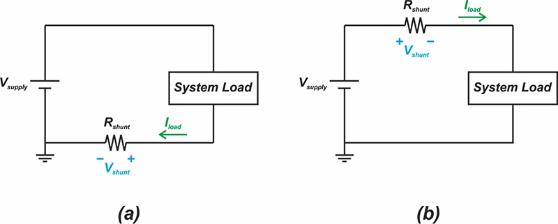
Low-side: simple but may disturb ground reference.
High-side: preferred in BMS or automotive, requires high common-mode capability.
Use dedicated current-sense amplifiers or differential op-amps for best accuracy.