How To Select Low resistance Shunt Resistors:in-depth Analysis Of Applications In Three Major Industries

Low resistance shunt resistors, with their exceptional measurement accuracy and minimal power loss, have become indispensable in precise current monitoring systems. Whether you’re integrating the smallest shunt unit for space-constrained electric vehicle BMS boards, a high-power device in a solar inverter, or a rugged resistor in industrial automation equipment, knowing how to choose the appropriate low-ohm shunt resistor for your specific application ensures the optimal balance of cost, performance, and reliability.
The working principle and key parameters of shunt resisto
1.working principle
The shunt resistor converts the current into a tiny voltage drop (V = I × R), and the voltage signal is collected by the back-end amplifier or ADC to achieve current measurement.
2.kernel parameter
Resistance value (R) : Usually lower than 5 mΩ, the lower the loss, but the weaker the voltage drop, and the higher the requirements for the amplification circuit.
Tolerance: It ranges from 0.5% to 5%. The higher the tolerance, the more expensive the price. The trade-off should be made based on the system's tolerance.
Temperature coefficient (TCR) : Unit ppm/° C. The smaller the TCR, the weaker the influence of temperature changes on the resistance value.
Rated power (P) : It determines the continuous current-carrying capacity. The heat generation can be calculated based on I²R, and then the selection is determined according to the PCB or heat dissipation solution.
In-depth analysis of industry applications
1.Automotive electronics (BMS, on-board charging)
Demand characteristics: Wide current range (0-200 A), large ambient temperature span (-40 ℃ to +85 ℃), and extremely high requirements for accuracy and reliability.
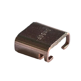
Typical selection: Through-hole shunt resistor with 0.5m Ω, 0.5% accuracy, TCR ±25 ppm/°C, and power ≥ 5 W.
Case: A well-known electric vehicle manufacturer adopted plug-in shunt resistors in the BMS, combined with copper flat laying under the PCB to enhance heat dissipation. Through hardware and software calibration, the measurement error was always controlled within ± 0.5A, effectively extending the battery life and increasing the driving range.
2.Industrial motor drive (servo control, frequency converter)
Demand characteristics: The transient current changes sharply, and the inrush current can reach 5 to 10 times the rated value. It is required that the shunt resistor has a fast transient response and low steady-state heat generation.
Typical selection: 1 mΩ - 2 mΩ, 1% accuracy, TCR ±50 ppm/°C, power ≥ 10 W high-power SMD shunt resistors, combined with through-hole heat dissipation design.
Key points to note: In the PCB layout, power traces and signal traces should be separated, and differential amplifiers should be used to reduce common-mode interference.
3.Power management (UPS, inverter, DC-DC)
Demand characteristics: Sensitive to efficiency, significant heat accumulation under continuous load, and needs to take into account resistance value, power and thermal resistance.
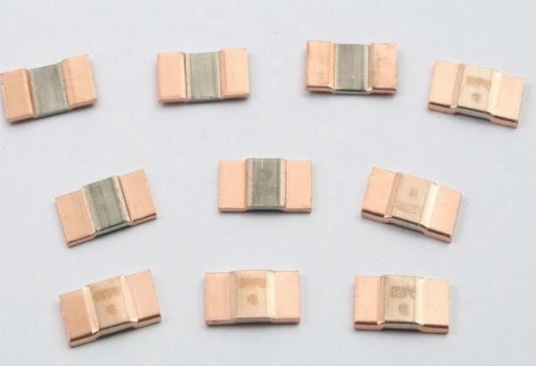
Typical selection: Low-footprint SMD shunt resistors with 0.2m Ω - 0.5m Ω, 0.5% accuracy, TCR ±30 ppm/°C, and power of 3-5 W.
Layout suggestion: Add large areas of copper foil at both ends of the resistance value, and lay a hot layer at the bottom layer, and connect for heat dissipation through vias. If the temperature exceeds the limit, a micro fan or heat sink can be installed.
Five considerations when selecting a model
1.Working current and power margin

Calculate the calorific value
For the given current peak value Imax The thermal power generated on the shunt resistor is:
P=I2max×R
For example: If Imax=100A,select and use R=0.5 mΩ
be P=1002×0.0005=5 W
Power margin setting
To avoid long-term overload and temperature accumulation, a margin of 20% to 30% should be reserved on the basis of the rated power.
If the nominal power is 5 W, then in reality, a model with a power of ≥6 W should be selected, or the temperature rise should be reduced through heat dissipation design.
Transient and continuous power
Pay attention to distinguishing between short-term impulse current (such as the moment of motor startup) and continuous operating current. If the inrush current is much higher than the continuous current, you can choose the plug-in type or the version with a heat sink that has a higher inrush capacity.
2.Measurement accuracy and system tolerance
accuracy class
High-precision scenarios (medical, automotive BMS) : 0.1% - 0.5%
General industrial scenarios (UPS, inverters) : 1% - 5%
System error allocation
In addition to the error of the shunt resistor itself, the sampling error of the amplifier, ADC and power supply jitter, etc. should also be taken into consideration.
For example: If the total error budget is ±1%, the accuracy of the shunt resistor can be allocated ±0.5%, and the rest is borne by the signal processing chain.
long term drift
The accuracy grade indicates the initial error, and drift will occur after long-term use. Select models with a "long-term stability" label (such as 0.1%/1000 h) for critical applications.
3.Temperature coefficient (TCR) and Environmental adaptability
The influence of TCR on measurement
The temperature coefficient (usually expressed in ppm/℃) reflects the influence of temperature changes on the resistance value.
ΔR=Rnominal×TCR×ΔT
such as R=1 mΩ、TCR=50 ppm/℃,When the temperature rises by 40 ℃,ΔR=0.001×50e-6×40=2e-6Ω.(Equivalent to a 0.2% change)
Extreme environmental considerations
Wide-temperature application: When the temperature range is from -40 ℃ to +125 ℃, TCR ≤ ±25 ppm/℃ should be selected
Frequent thermal cycling: In fields such as aerospace and military industry, dedicated models with "thermal shock" certification are preferred
Software compensation strategy
In the MCU, a temperature sensor is used to read the PCB temperature, and the measured value is dynamically adjusted according to the preset TCR curve.

4.Packaging form and PCB layout
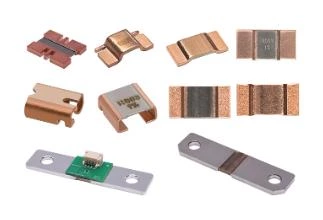
SMD vs Plug-in Type
SMD: Suitable for space-constrained and small and medium current (< 50 A) applications, with high automation in the surface mount technology (SMT) process.
Plug-in type: Excellent surge resistance and impact resistance, suitable for high current (> 100A) or scenarios requiring better heat dissipation.
Thermal management design
Via heat dissipation: A large number of vias are arranged at both ends of the SMD resistance value and connected to the large copper surface at the bottom layer.
Heat sink and air duct: The plug-in type can be equipped with a metal heat sink or placed in the air flow channel.
Wiring and flooring
The shortest path: The current loop wiring should be the shortest and widest.
Separate signal ground: The measurement ground is independent of the power ground to avoid ground loop voltage interference.
5.Cost and Supply Chain
Unit Price vs Benefit
For high-frequency and small-batch projects, high-precision and brand premium models can be given priority. When mass-producing, it is necessary to balance performance and unit price, and B-class or C-class devices are commonly used.
Delivery date and availability
Pay attention to the inventory and delivery time of mainstream platforms (Digi-Key, Mouser, Arrow). Sometimes, secondary brands with the same parameters can be accepted to shorten the delivery cycle.
Certification and Compliance
For fields such as automobiles and medical care, models that comply with certifications such as ISO 26262, EC-Q200, and UL should be selected to avoid the high cost of re-verification in the later stage.