Prosemi CSR ALMJ20 Current Sensing Resistors For Automotive Applications
Publish Time:
In the electronic systems of new energy vehicles and traditional vehicles, Automotive Current Sensing Resistors play a crucial role. They convert the current from key modules such as the motor, BMS, and ECU into precise voltage signals, providing real-time feedback to the subsequent controller to ensure the safe and efficient operation of the vehicle under conditions such as starting, braking, and regenerative braking.
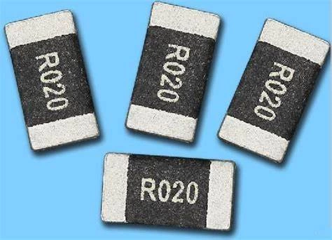
Product Presentation
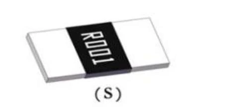
Thick Copper-Conductor Metallized Construction
By harnessing state-of-the-art metallization processes, we lay down a precision-engineered copper foil layer up to 25 µm thick directly onto a high-performance ceramic or polymer substrate. This thick-film construction not only elevates the resistor’s continuous current capacity—often by 30 % or more compared to conventional thin-film devices—but also minimizes Johnson noise and thermal-EMF effects. The tightly bonded copper conductor exhibits exceptional thermal conductivity, enabling rapid heat dissipation under high-load conditions and extending long-term stability even in power-cycling environments. As a result, these resistors excel in applications demanding both high current throughput and low electrical noise—such as battery-management systems in electric vehicles, precision motor-control circuits in industrial machinery, and high-efficiency DC-DC converters—ensuring your design meets its performance targets without compromise.Ultra-Long-Term Stability
Employing a comprehensive accelerated-life testing regimen, our resistors endure hundreds of hours of combined high-temperature, high-humidity exposure and prolonged power-aging cycles at rated load. Even after 1,000 hours under these punishing conditions, typical resistance drift measures less than ±0.1 %, a figure so low it effectively eliminates performance degradation over the product’s service life. This ultra-long-term stability eradicates the need for periodic recalibration or component swaps, translating to lower maintenance costs and uninterrupted uptime—even in the most demanding applications, from under-hood automotive modules and industrial process controls to renewable-energy inverters and aerospace avionics. When system reliability is non-negotiable, count on our resistors to deliver unwavering precision year after year.RoHS-Compliant, Halogen- and Lead-Free
The material formulation strictly adheres to environmental standards, contains no halogens or lead, and complies with the latest RoHS directives—helping your products pass global regulatory reviews.Inherently Stable, High-Reliability Materials
Manufactured with high-purity metals and premium insulating substrates under rigorous process control and multi-stage quality inspections, each resistor exhibits uniform electrical and mechanical characteristics.High-Power Ratings
Available in power ratings from 1 W up to 10 W (and beyond), the ALMJ20 series lets you select the optimal device for high-current, high-power scenarios requiring accurate measurement.Ultra-Low Temperature Drift (Excellent TCR)
With a typical temperature coefficient of ±25 ppm/°C (or better), resistance remains virtually unchanged across –55 °C to +150 °C, providing a rock-solid foundation for precision current sensing. Thanks to these advantages, the ALMJ20 series Current Sensing Resistors are your premier choice for applications demanding both high precision and uncompromising reliability.Exceptional Trustworthiness
Leveraging a rigorous certification process and impartial third-party validation, our resistors have earned endorsements from leading international standards organizations — including IEC, UL, and AEC-Q200 — as well as specialized laboratories around the globe. Each device undergoes exhaustive environmental, thermal-shock, and long-term load testing to ensure that its resistance value remains rock-steady over the full automotive temperature range (–40 °C to +150 °C) and under high-frequency switching stresses. This unwavering stability makes them exceptionally well-suited for mission-critical systems, from anti-lock braking modules and advanced driver-assistance electronics to precision industrial feedback loops and high-density power-conversion networks. In demanding power-management scenarios where drift or failure is simply unacceptable, you can rely on our resistors to maintain peak performance and safeguard your system’s integrity, project after project.Product Characteristics
| Item | Test Condition / Methods | Limit | Standard |
|---|---|---|---|
| Temperature Coefficient of Resistance (TCR) | TCR = (R - R0) / R0(T2 - T1) × 10⁶R0: resistance at room tempR: resistance at 125℃T1: room tempT2: 125℃ | Refer to Spec | JIS-C 5201 |
| Short Time Overload | 5 × rated power for 5 seconds | ≤ ±0.5% | JIS-C5201-1 4.13 |
| Temperature Cycling | 1000 cycles (-55℃ to 125℃), 30 min at each extreme | ≤ ±0.5% | JESD22 Method JA-104 |
| Low Temperature Storage | -55℃ for 1000 hours, no power | ≤ ±0.5% | JIS C 5201 |
| High Temperature Storage | 1000 hours at 125℃,No power | ≤ ±1% | MIL-STD-202 Method 108 |
| Biased Humidity | 85℃±5℃, 85±5% RH 10% bias, 1000 hours ,at rated power 1.5 hours “ON”, 0.5 hours “OFF” , after standing 24±4 hours to measure the resistance change rate. | ≤ ±0.5% | MIL-STD-202 Method 103 |
| Operational Life | Apply the rated current to the 125±3℃ incubator for 1000 hours, and stand for 24±4 hours after removal to measure the resistance change rate. | ≤ ±0.5% | MIL-STD-202 Method 108 |
| Load Life | 70℃± 2℃, 1000 hours, at rated power 1.5 hours “ON”, 0.5 hours “OFF” , after taking it out and standing for more than 1 hour, the resistance change rate is measured. | ≤ ±1% | JIS-C5201 |
| Resistance to Solder Heat | 260℃± 5℃, time:10 ±1 sec, 1000 hours, after taking out and standing for more than 1 hour, measure the resistance change rate. | ≤ ±0.5% | MIL-STD-202 Method 210 |
| Solderability | Soak in the furnace at 245±5℃ for 3±1 sec .Take out and observe the solder area under amagnifying alass. | Solder coverage ≥95%, no damage | J-STD-002 |
| Joint Strength of Solder | Test item (Bendability test) Weld in the bending test plate, place on the bending test machine, press in the center of the test plate, and measure under load. | ≤ ±0.5% | JIS-C5201-1 4.32 |
| Experiment item 2 (Fixation test) Weld the resistance in the rigidity test plate, place it on the end electrode test machine, apply the force in the direction of the force with the test probe with the radius of R0.5, and maintain 10 sec, andmeasure the resistance change rate under the load. | ≤ ±0.5% | JIS-C5201-1 4.32 |