Prosemi AC Power Port Surge Protection Solutions: Technical Breakthroughs and Application Advantages
Integrated TSS + MOV Surge Protection Solution
As a key interface connecting electronic equipment to the power grid, the AC power port’s surge protection directly impacts equipment safety, operational stability, and personnel protection. In real-world scenarios, lightning strikes or normal equipment operation can generate high-energy surges of 10–100 kA. Without effective protection measures:
-
Minor cases can cause damage to core electronic components, power interruptions, and economic losses.
-
Severe cases may result in circuit failures leading to fires, electric shocks, and other safety hazards that endanger human life.
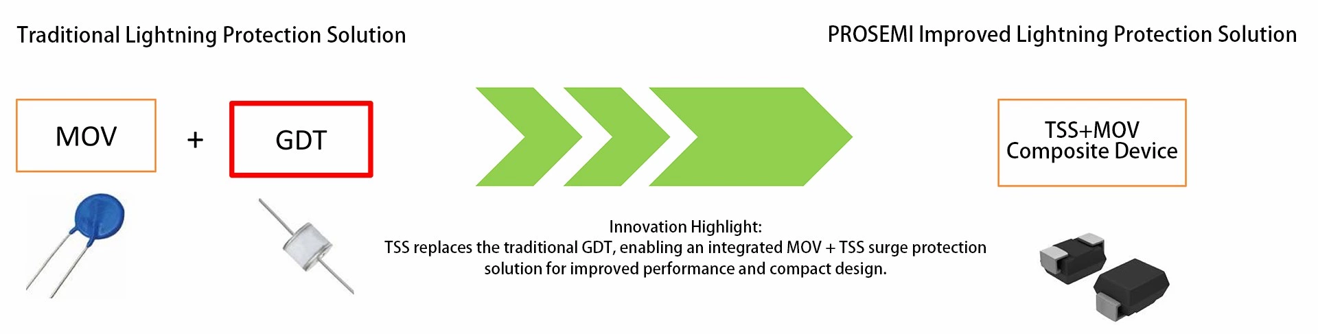
Traditional surge protection solutions mainly rely on a combination of Metal Oxide Varistors (MOVs) and Gas Discharge Tubes (GDTs). However, the inherent performance limitations of these components can no longer meet the current requirements for surge reliability and compact design in modern electronic equipment.
To address this, Prosemi Micro-electronic has introduced an integrated TSS + MOV surge protection design, achieving breakthroughs in response speed, reliability, and size—offering superior protection for AC power ports.
Limitations of Traditional AC Power Port Surge Protection Solutions
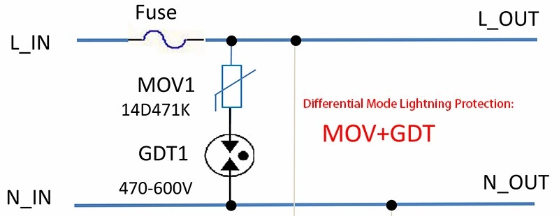
At present, the mainstream traditional surge protection configuration in the industry is the “471 MOV (470 V) + 470 V–600 V GDT in series” design. While this approach allows the GDT to reduce the leakage current of the MOV—thereby extending the MOV’s service life to some extent—the inherent performance limitations of both the MOV and the GDT still compromise the overall protection effectiveness.
㈠ Core Limitations of MOV:
The performance stability of MOVs is significantly affected by electrical stress and thermal cycling. During long-term use, two major issues tend to occur:
-
Performance degradation: Over time, the MOV’s leakage current gradually increases and its clamping voltage drifts, leading to reduced surge suppression capability.
-
Current imbalance risk: When multiple MOVs are connected in parallel for high-current applications, differences in aging rates among the MOVs can cause uneven current distribution, resulting in some MOVs becoming overloaded and failing prematurely.
㈡ Core Limitations of GDT (Gas Discharge Tube):
Compared with MOVs, the performance shortcomings of GDTs are even more pronounced, directly limiting the reliability and applicability of this “commonly used configuration”:
-
Sustained current risk: After a GDT conducts, if the circuit’s DC voltage is higher than its hold voltage, the device cannot automatically turn off, remaining in a conducting state and potentially causing a short circuit that damages downstream circuits.
-
Large breakdown voltage tolerance: The breakdown voltage tolerance of GDTs is typically ±20%–±30%. Designers must reserve a large safety margin to ensure effective protection, increasing circuit design complexity.
-
Slow response and high residual voltage: GDTs have a response time of ≤100 ns. In fast-rising surge conditions, the dv/dt effect can generate high residual voltage, making it difficult to effectively clamp surge energy and possibly damaging downstream sensitive components.
-
Bulky size: GDTs are physically large, making them unsuitable for space-constrained devices such as PD fast chargers and compact power supplies.
More importantly, even though the “471 MOV + 470 V–600 V GDT” configuration is the most common series setup, the parameters of the two components are difficult to precisely match—variations in MOV leakage current and fluctuations in GDT breakdown voltage offset each other’s cooperative advantages. This ultimately leads to reduced overall surge protection performance, falling short of the lightning protection requirements of high-end equipment.
TSS (Thyristor Surge Suppressor): A New-Generation Core Device for Surge Protection
(1) Working Principle of TSS
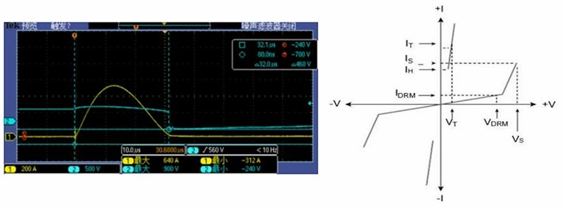
The operating states of a TSS in a circuit can be divided into three stages: normal operation, surge protection, and automatic recovery.
-
Normal Operation Stage:
The TSS remains in an off state, allowing only nanoamp-level leakage current to pass through, without interfering with the circuit’s normal operation. -
Surge Protection Stage:
When an overvoltage surge occurs and the voltage exceeds the TSS breakdown voltage (VBO), the internal PN junction undergoes avalanche breakdown and switches on rapidly—within 10 ns. Once conducting, the TSS exhibits milliohm-level low resistance, safely diverting surge currents of 10–100 kA and clamping the voltage to a low on-state voltage (VTM). -
Automatic Recovery Stage:
After the surge energy dissipates and the circuit current drops below the TSS holding current (IH), the TSS immediately switches off and returns to a high-resistance state, achieving “no follow current protection.” The circuit automatically resumes normal operation without any manual intervention.
(2) Comparison of Turn-Off Mechanisms Between TSS and GDT
Although both TSS and GDT are switching-type surge protection devices, their turn-off mechanisms differ fundamentally—this distinction is the key reason why TSS can enhance the performance of traditional “common configurations”:
-
GDT – Voltage Turn-Off:
As the core component in traditional configurations, a GDT turns off only when the external voltage crosses zero. After conduction, the external voltage is directly applied to the MOV, meaning that if the voltage does not reach zero, continuous follow current is likely to occur, potentially leading to circuit faults. -
TSS – Current Turn-Off:
The TSS turn-off depends solely on a current threshold—when the surge current drops below the holding current (IH), it immediately shuts off through thermal action. This enables much faster recovery and fundamentally eliminates the risk of continuous conduction, addressing a critical weakness of traditional configurations.
Prosemi Integrated MOV + TSS Surge Protection Solution: Innovative Design Concept
To meet the needs of devices such as PD fast chargers that demand both compact design and high surge protection performance, Prosemi has introduced an integrated MOV + TSS surge protection solution—aimed at optimizing the traditional configuration. In this design, the conventional GDT is replaced by a TSS, using an optimized combination of 331 MOV (330 V) + 275–600 V TSS, and adopting a deeply integrated structure that aligns with the industry’s ongoing trends of miniaturization, surface-mount technology (SMT) compatibility, cost reduction, and multifunctionality.
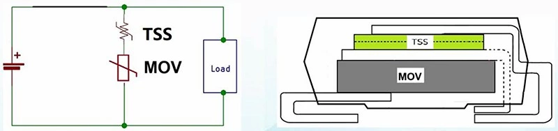
This integrated solution is not a simple component stack, but rather a carefully engineered coordination between the MOV and TSS. The two components work synergistically to not only overcome the performance limitations of traditional GDT-based configurations but also satisfy the dual demands of automated manufacturing and enhanced product safety:
-
Manufacturing efficiency:
The integrated architecture is directly compatible with SMT automated production lines, reducing manual soldering steps required by discrete components. This lowers production errors and costs while improving overall efficiency. -
Enhanced surge reliability:
Through precise coordination and matched parameters between components, the integrated design improves surge protection reliability both structurally and functionally, eliminating the risks of protection failure caused by component misalignment or parameter mismatch in discrete configurations.
Technical Advantages ( TSS 380V+MOV 330V )
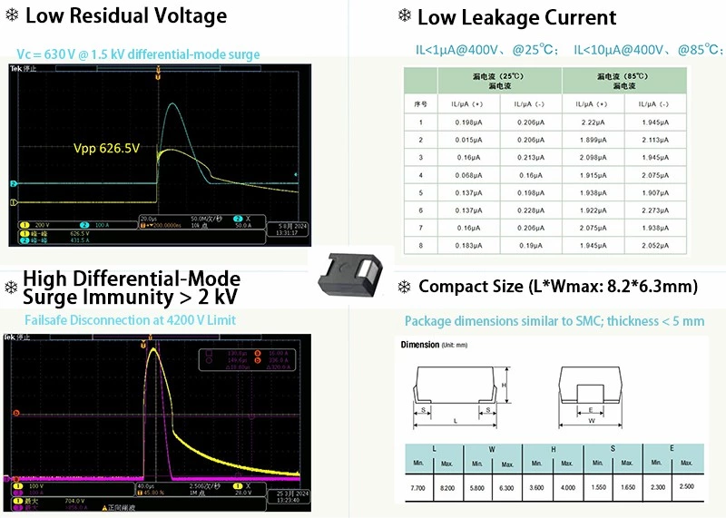
AC Power port - Performance Metrics / Comparative Analysis
| Item | Traditional Lightning Protection Solution | PROSEMI Improved Lightning Protection Solution |
|---|---|---|
| L, N Line Device Configuration | 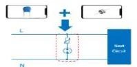 |
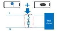 = = |
| Component Combination | 471 MOV ( 470V ) + 470V ~ 600V GDT | 331 MOV ( 330V ) + 275V ~ 600V TSS |
| Performance Analysis | 1. GDTs have large breakdown voltage tolerances (±20%–±30%), requiring sufficient design margin to ensure reliable protection. 2. GDT response time is relatively long (≤100 ns), and due to the surge waveform’s dv/dt effect, the resulting residual voltage tends to be high. |
1. Reduced Residual Voltage: Compared with GDTs, the TSS offers an extremely fast response time and much smaller breakdown voltage tolerance, resulting in a significantly lower residual voltage. |
| 3. The advantage of using GDT in combination with MOV is that it helps reduce MOV leakage current, thereby extending the MOV’s service life. | 2. Low Leakage Current: With the TSS + MOV combination, the number of test cycles before the MOV leakage current increases to around 4.5 μA is 4.3 times higher than that of a single MOV and 1.4 times higher than that of a GDT + MOV combination. |
|
| 3. High Reliability: With the TSS + MOV combination, the number of surge endurance cycles before MOV aging occurs is 4.4 times greater than that of a single MOV and 1.5 times greater than that of a GDT + MOV combination. The TSS plays a more significant role in extending the MOV’s service life and ensuring long-term stability. |
||
| 4. Large Footprint, Unfavorable for Miniaturized Design: The large physical size occupies more space, making it unsuitable for compact or miniaturized product designs. |
4. Compact Size: The integrated design saves at least 50% of the space compared with discrete MOV + GDT solutions. |
Real-World Applications / Use Cases
The Prosemi Integrated Solution — Designed Specifically for Differential-Mode Surge Protection in 220 Vac Power Ports.
Differential-mode surge protection focuses on suppressing surge currents and overvoltages generated between the two power lines (e.g., live and neutral) at the AC power port, preventing damage to internal circuits. The Prosemi integrated MOV + TSS solution is precisely engineered to address real-world surge protection challenges across the following key application scenarios:
⑴ PD Fast Chargers
Core Requirement:220 Vac input ports must provide reliable differential-mode surge protection while maintaining a compact size (e.g., mini fast chargers) and safeguarding sensitive internal chips (such as fast-charging protocol ICs).
Solution Value:
-
Saves 50% board space, perfectly fitting compact charger designs.
-
Low residual voltage effectively protects delicate fast-charging chips from surge impact, preventing function loss due to lightning or power fluctuations.
-
Fully compatible with automated SMT production, supporting high-efficiency mass manufacturing of fast chargers.
⑵ Power Strips (Extension Sockets)
Core Requirement:
Both the 220 Vac main input and individual output ports require differential-mode surge protection. Long-term powered operation demands high reliability to prevent surges from damaging connected devices (such as smartphones, computers, or household appliances).
Solution Value:
-
Provides 4.4× higher surge endurance reliability, ensuring long-term stable protection without frequent component replacement.
-
Integrated compact design saves internal space, allowing more socket outlets to be added.
-
Fully supports automated assembly lines, improving production efficiency and consistency.
⑶ Compact 220 Vac Power Devices
Core Requirement:
Smart home power modules (e.g., smart speaker or camera power supplies) and small industrial control power units require stable differential-mode surge protection in a limited space while maintaining reliable long-term operation.
Solution Value:
-
Miniaturized integrated structure fits seamlessly into compact device layouts.
-
4.3× improved leakage current control extends surge protector lifespan, reducing maintenance frequency.
-
Ensures long-term safety and stability across the entire 220 Vac power supply chain.
Conclusion
The Prosemi Integrated MOV + TSS Surge Protection Solution is specially designed for differential-mode surge protection in 220 Vac power ports. Through TSS device innovation and integrated design, it directly addresses the three major pain points of the traditional “MOV + GDT” configuration — high residual voltage, MOV aging, and large component size. This solution is particularly suited for applications such as PD fast chargers and power strips, while also meeting the dual requirements of automated manufacturing and high product safety, providing a new and upgraded path for AC power port surge protection.
At present, the integrated MOV + TSS component has completed development and is ready for practical application. If you would like to:
-
Obtain detailed datasheets and learn more about TSS operating characteristics, breakdown voltage tolerance, and other technical specifications;
-
Understand pricing and cost-performance benefits of the integrated solution;
-
Request free samples for compatibility testing to verify residual voltage control and spatial fit;
Please feel free to contact us directly:
Email: nancy.chen@prosemitech.com
Website: https://www.prosemicsr.com/thyristor-surge-suppressors
Prosemi always upholds the philosophy of “Customer First,” committed to providing high-quality, customized surge protection solutions. Our goal is to help your 220 Vac devices (such as PD fast chargers and power strips) upgrade from “basic protection” to “high-reliability, miniaturized surge protection,” giving you a competitive edge in the market.
We look forward to partnering with you to create a safer and more reliable electronic device ecosystem.