Bridge Rectifier Explained: Principles, Performance, And Selection Guide
1. What Is a Bridge Rectifier?
A bridge rectifier is a circuit that converts alternating current (AC) into pulsating direct current (DC) using four diodes arranged in a bridge configuration. Compared with half-wave or center-tap full-wave rectifiers, a bridge rectifier delivers current to the load during both positive and negative halves of the AC cycle, making it an efficient and cost-effective solution.
2.Working principle of a bridge rectifier
The four diodes—D1, D2, D3, and D4—are connected so that:
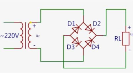
In the first positive half cycle of the AC signal, the diodes D2 and D3 become forward biased and start conducting. At the same time, the diodes D1 and D4 will be reverse biased and will not conduct. The current will flow through the load resistor via the two forward-biased diodes. The voltage seen at the output will be positive at terminal d and negative at terminal c.
Now, during the negative half cycle of the AC signal, the diodes D1 and D4 will be forward biased and diodes D2 and D3 will become reverse biased. The positive voltage will appear on the anode of D4, and negative voltage will be applied to the cathode of D1. It is worth noting at this point that the current that will be flowing through the load resistor will have the same direction as it has with the positive half cycle. Therefore, no matter the polarity of the input signal, the output polarity will always be the same. We can also say that the negative half cycle of the AC signal has been inverted and is appearing as a positive voltage at the output.
3.Comprehensive Characteristics of the Bridge Rectifier
A bridge rectifier is a fundamental circuit for converting AC to DC. Its characteristics can be understood from two perspectives: Macroscopic Application Advantages (explaining why it is widely adopted) and Microscopic Performance Parameters (providing the basis for quantitative analysis and design).
Part I: Core Application Advantages (Why Choose It?)
These characteristics explain the key engineering benefits of the bridge rectifier.
(1)Full-Wave Rectification
Nature: Utilizes both the positive and negative half-cycles of the AC input for complete energy conversion.
Advantages:
- Continuous Output: Load current flows in a single, uninterrupted direction.
- Higher Ripple Frequency: The output ripple frequency is twice the input AC frequency (e.g., 50Hz input → 100Hz ripple). This makes subsequent filtering easier and more cost-effective.
(2)No Center-Tap Transformer Required
Nature: This is a structural advantage over other full-wave rectifier topologies (e.g., center-tapped full-wave rectifier).
Advantages:
- Lower Transformer Cost: Requires only a simple two-wire secondary winding, eliminating the need for a center tap.
- Compact Size & Versatility: Can be connected directly to a standard single-phase AC source, simplifying power supply design.
(3)Higher DC Voltage
Comparative Analysis: For the same transformer secondary RMS voltage (Vrms):
- Bridge Rectifier Output: Vdc ≈ 0.9 × Vrms
- Center-Tapped Rectifier Output: Vdc ≈ 0.45 × Vrms (because it uses only half the winding voltage per half-cycle)
Engineering Implication: To achieve the same output voltage, a bridge rectifier can use a transformer with a lower voltage rating, saving further cost and space.
(4)Diode Voltage Drops
Peak Inverse Voltage (PIV): Each diode must withstand PIV = Vm (the peak input AC voltage). This requirement is more reasonable than that for a half-wave rectifier.
Average Forward Current: Each diode conducts for only one half-cycle, so its average current is only half the load current: Id(avg) = 0.5 × I_load.
(5) Primary Loss Source: Diode Forward Voltage Drop
Nature: In any conduction path, current flows through two diodes in series.
Impact: For silicon diodes, this creates a fixed voltage drop loss of approximately 1.4V (2 × 0.7V).
Critical Domain: This loss is particularly significant in low-voltage, high-current rectification applications and is a primary factor affecting overall efficiency.
Part II: Key Performance Parameters (How to Analyze and Design It?)
These characteristics provide the three core theoretical metrics for quantitatively evaluating a bridge rectifier's performance.
(1) Ripple Factor (γ)
Definition: A dimensionless parameter measuring the magnitude of the residual AC component (ripple) in the DC output. A lower value indicates a smoother, more stable output.
Theoretical Formula (without filter capacitor):
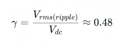
Engineering Significance: It is the direct basis for selecting the subsequent filter circuit (e.g., capacitor size). Its frequency advantage (doubled frequency) means a smaller capacitor can achieve the same filtering effect.
(2)Peak Inverse Voltage (PIV)
Definition: The maximum instantaneous reverse voltage a diode can withstand while reverse-biased. This is a critical safety parameter for component selection.
Calculation Formula:
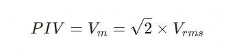
Component Selection: The selected diode's repetitive peak reverse voltage rating must exceed this calculated value with a sufficient safety margin.
(3)Rectification Efficiency (η)
Definition: The ratio of DC output power to AC input power, measuring the effectiveness of energy conversion.
Calculation Formula:
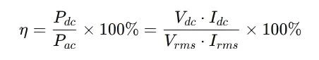
Theoretical Maximum: The maximum theoretical efficiency for an ideal bridge rectifier (ignoring diode drops and transformer losses) is approximately 81.2%.
Practical Efficiency: Actual efficiency is lower due to diode forward voltage drops and transformer copper/core losses.
4. Applications of Bridge Rectifier
Here are some key applications of bridge rectifiers:
- Used in power adapters for laptops, phones, and other electronic devices.
- Convert AC power from outlets into DC power to charge batteries.
- Provide DC power for motors and control systems in factories.
- Used in vehicles for charging batteries and powering car accessories.
- Found in appliances like refrigerators, washing machines, and air conditioners.
- Used in LED drivers and lighting control circuits.
- Convert AC signals into DC for audio and radio amplifiers.
- An essential component in various electronic devices and circuits.
- Convert AC power generated by solar panels into DC for use or storage.
- Part of uninterruptible power supplies (UPS) to provide emergency power during outages.
- Used to provide DC power for welding equipment.
- Found in medical equipment like X-ray machines and MRI scanners.
- Used in power supplies for telecom equipment and data centers.
5. How to Choose the Right Bridge Rectifier
Bridge Rectifier: Advantages vs. Disadvantages
| Advantages | Disadvantages |
|---|---|
| High-Efficiency AC-to-DC Conversion Highly efficient at converting AC to DC, providing a consistent and stable power supply. |
Inherent Higher Voltage Drop Exhibits a larger voltage drop (~1.4V for silicon diodes) compared to other rectification methods, leading to some power loss. |
| Compact and Space-Efficient Design Requires only four diodes, resulting in a simple, highly integrable structure suitable for space-constrained applications. |
Significant Heat Generation in High-Power Applications Generates considerable heat in high-power scenarios, often requiring additional cooling measures (e.g., heat sinks or fans). |
| Full-Wave Rectification Utilizes both the positive and negative halves of the AC waveform, producing a smoother DC output with lower ripple. |
Reduced Efficiency at Low Voltages The fixed diode drop becomes a significant percentage of the input voltage in low-voltage applications, reducing overall efficiency. |
| No Center-Tapped Transformer Needed Eliminates the need for a center-tapped transformer (unlike center-tap rectifiers), simplifying wiring and reducing cost. |
Unsuitable for High-Frequency AC Input Diode switching speed can be a limiting factor, making it less ideal for high-frequency AC inputs. |
| Standardized and Readily Available A very common, standard component that is low-cost, widely available, and ideal for various electronic projects. |
Requires Special Considerations for High-Current Applications For high-current loads, special arrangements (e.g., diode paralleling) or dedicated modules may be needed to handle the current and thermal stress effectively. |
Summary and Selection Guidance
The bridge rectifier is the standard choice for most low-to-medium power, line-frequency (50/60Hz) AC-to-DC applications due to its high efficiency, full-wave operation, compactness, and lack of a center-tap requirement. Its integrated module (bridge rectifier package) is particularly convenient.
However, its inherent forward voltage drop and switching speed limitation make it less suitable for low-voltage supplies, high-frequency operation, or very high-power scenarios. In such cases, alternatives like synchronous rectification (using MOSFETs instead of diodes) or other advanced topologies may be considered.
Key Selection Logic & Component Sizing Checklist
When designing with or selecting a bridge rectifier, follow this integrated logic and checklist:
Step 1: Application Suitability Check
Ideal For: General-purpose, mains-frequency (50/60 Hz), low-to-medium power applications.
Reconsider For:
- Very low output voltages (e.g., < 5V) where the ~1.4V diode drop causes significant efficiency loss.
- High-frequency AC inputs (beyond tens of kHz).
- Very high-current applications demanding exceptional thermal management.
Step 2: Critical Diode / Module Parameters
If a bridge rectifier is suitable, ensure the selected diodes or integrated module meet these specifications:
(1)Average Forward Current (IF(AV))
Rule: Rated IF(AV) must exceed the calculated average load current by a 20–50% safety margin. (Note: Each diode carries half the total DC load current.)
(2)Peak Repetitive Reverse Voltage (VRRM / PIV)
Rule: The VRRM rating must be at least 1.5 times the maximum peak AC input voltage (Vpk = √2 × Vrms) to handle transients and ensure reliability.
(3)Forward Voltage Drop (Vf)
Optimization: For higher efficiency, especially in low-voltage designs, select diodes with a low Vf (e.g., Schottky diodes).
(4)Thermal Management
Analysis: Calculate power dissipation (P_loss ≈ 2 × Vf × I_load).
Action: Based on thermal resistance (θJA), design adequate cooling (heatsink, PCB copper area) to keep junction temperature within limits.
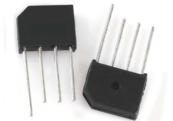
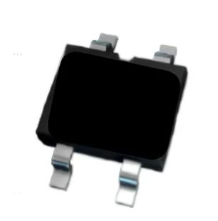
(5)Package Selection
Low Current: SMD or small through-hole packages (up to a few amps).
High Current: Dedicated power modules with bolt-down or large packages for heatsinking.
Step 3: Final Design Validation
Verify the complete design meets output ripple, voltage, and efficiency targets.
For non-standard applications (high frequency, very high power), confirm diode dynamic characteristics (reverse recovery time) and thermal design are adequate, or finalize the choice of an alternative topology.
7. Conclusion
Bridge rectifiers combine simplicity, efficiency, and low cost, making them the go-to choice for converting AC to DC in a wide range of power supplies. By selecting the right current and voltage ratings, managing heat effectively, and following good PCB layout practices, you can achieve reliable and efficient DC power for your designs.