Understanding Power Loss And Heat Management In Shunt Resistors
In any current measurement circuit, managing power loss and heat generation is critical for maintaining accuracy and long-term reliability. Shunt resistors, which are placed in series with the current path to measure current flow, inevitably dissipate power as heat.
Understanding how this power loss occurs—and how to control it—helps engineers design safer and more efficient electronic systems.
What Causes Power Loss in a Shunt Resistor
Power loss in a resistor is mainly due to the electrical energy converted into heat as current passes through the resistor.
The relationship follows the well-known equation:
P = I² × R
Where:
- P= power loss (in watts)
- I= current (in amperes)
- R= resistance (in ohms)
Because shunt resistors typically have very low resistance values (from micro-ohms to milliohms), power loss may seem small, but in high-current applications, even a small R can lead to significant heating.
Effects of Power Loss and Overheating
When power loss turns into heat, several performance issues can arise:
- Temperature Drift: The resistance value changes with temperature, leading to inaccurate current readings.
- Thermal Stress: Continuous overheating may cause long-term resistance drift or physical damage.
- Reduced Lifespan: Prolonged exposure to high temperatures accelerates material degradation.
For precision applications such as EV battery monitoring, energy storage systems, or industrial power converters, even minor temperature changes can significantly affect system accuracy.
Selecting the Right Shunt Resistor to Minimize Power Loss
(1) Choose an Optimal Resistance Value
Select the lowest possible resistance that still allows a measurable voltage drop.
For instance, in a 100A circuit:
- Using a 0.5 mΩ resistor → Power loss = 100² × 0.0005 = 5W
- Using a 1 mΩ resistor → Power loss = 10W
Lower resistance reduces heat, but be sure your sensing circuit can still detect the voltage drop accurately.
(2) Check the Power Rating
Always select a shunt resistor with a power rating at least 2–3 times higher than the expected dissipation.
This provides a safety margin for transient currents and prevents overheating during overload conditions.
(3) Pay Attention to TCR (Temperature Coefficient of Resistance)
Low TCR values (typically below 50 ppm/°C) ensure the resistance value stays stable as temperature rises.
Metal alloy materials such as Mn-Cu or Ni-Cr alloys are ideal for minimizing temperature drift.
(4) Optimize PCB Layout and Cooling
Good thermal design helps distribute heat evenly:
- Use wide copper traces to spread heat.
- Add thermal vias or heat sinks for high-current circuits.
- Ensure proper airflow around the resistor area.
Heat Management Techniques
Managing thermal buildup is as important as selecting the right component. Some proven methods include:
- Using bolt-on or chassis-mounted resistors for better heat conduction.
- Employing metal alloy resistors with low thermal EMF and stable heat dissipation.
- Monitoring surface temperature during testing to ensure the resistor stays within rated limits.
Designers should always verify thermal behavior using simulation or empirical testing under real load conditions.
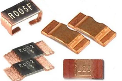
Why Metal Alloy Shunt Resistors Offer Better Heat Stability
Compared with traditional manganin or copper types, metal alloy shunt resistors provide superior thermal stability due to:
- Lower TCR and thermal EMF
- Uniform internal structure for even heat distribution
- Excellent long-term resistance drift performance
These advantages make them ideal for high-current, high-precision applications such as automotive, energy storage, and industrial power systems.
Conclusion
Effective heat management and power loss control are essential for maintaining current measurement accuracy and ensuring the longevity of your electronic system.
By selecting low-TCR, high-stability metal alloy shunt resistors—and combining them with thoughtful thermal design—you can achieve reliable performance even under demanding load conditions.