Prosemi Micro-electronic Announces The Launch Of Its Ultra-thin Film Fuse Featuring Ultra-low Dcr
Introduction
At present, lightweight and compact design has become a mainstream trend across multiple industries, including consumer electronics, automotive electronics, medical electronics, and industrial control. These sectors are placing increasingly stringent demands on the size and performance of components.
Take smartphones as an example: powered by lithium batteries, they continue to integrate richer functions while requiring ever-lower power consumption. This has driven the need for fuses with ultra-low internal resistance. Similarly, in automotive electronics (in-vehicle devices), medical electronics (portable diagnostic instruments), and industrial control (miniaturized controllers), manufacturers face the dual challenge of limited space and the pursuit of higher energy efficiency — making compact, low-loss components essential.
In response to these common industry challenges, Prosemi Micro-electronic has optimized its production process and successfully developed an ultra-thin film fuse with ultra-low DCR (Direct Current Resistance). This new product not only provides reliable circuit protection for devices in consumer, automotive, medical, and industrial fields, but also:
• Fits seamlessly into space-constrained designs thanks to its ultra-thin structure,
• Reduces energy loss through its ultra-low DCR characteristics,
• And helps manufacturers achieve cost reduction and efficiency improvement.
By combining compact design with high performance, Prosemi’s ultra-thin film fuse offers strong support for the continued drive toward lightweight, efficient electronic devices across multiple industries.
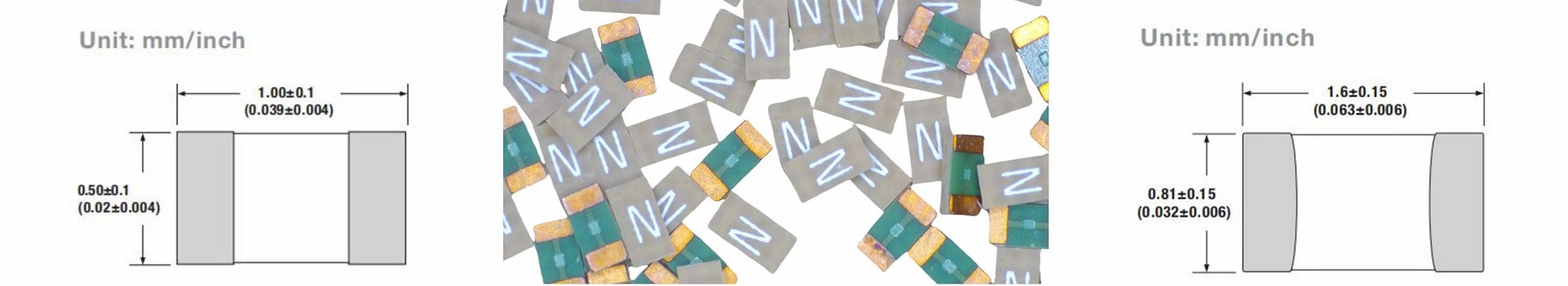
Key Features & Specifications
(1) Electrical Performance & Protection Characteristics
• Ultra-Low DCR (Direct Current Resistance): Effectively reduces current loss and voltage drop, meeting the needs of low-power devices.
• High Inrush Current Withstanding Capability: Handles instantaneous surge currents at device start-up, preventing false triggering of protection.
•Fuse Types and Response Characteristics
⒈ Fast-Acting (Fast Blow): Provides rapid circuit interruption under 200% overload current. Suitable for applications requiring high sensitivity to overload conditions, such as precision ICs and sensor circuits. Ensures quick disconnection of fault currents to protect sensitive components.
⒉ Time-Delay (Slow Blow): Withstands short-duration inrush currents, such as those occurring during motor or capacitor start-up. Ideal for equipment where brief surge currents are expected but normal operating current remains stable, e.g., automotive motors and drive modules in industrial control. Prevents nuisance tripping and ensures reliable operation during startup.
• High Reliability: Provides stable performance for long-term operation across multiple industries, reducing the risk of equipment failure.
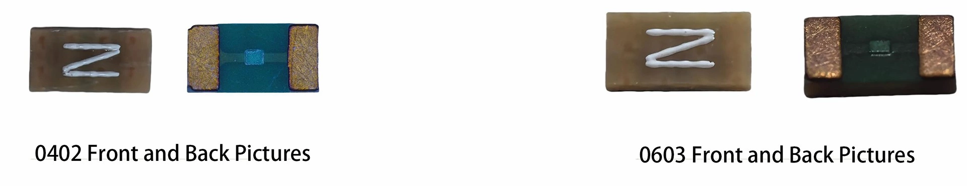
(2) Structural & Material Design
• Fiberglass-Reinforced Epoxy Fuse Body: Enhances heat resistance and impact strength, making it suitable for complex operating environments.
• Copper Terminations with Nickel and Tin Plating: Ensures lower contact resistance, superior oxidation resistance, and excellent soldering reliability.
(3) Environmental Compliance
• Halogen-Free, RoHS Compliant, and Lead-Free: Meets global environmental regulations, making it suitable for consumer electronics, medical, and automotive applications where strict environmental standards are required. Supports manufacturers in achieving sustainable production goals.
| Part No. | Current Range (A) | Rated Voltage (VDC) | Interrupting Rating | Typical Cold DCR (Ω) | Typical I²t (A²Sec)* | Type |
| 0402FA-R500-L | 0.5 | 35 | 35A@35V | 0.165 | 0.007 | Fast Acting |
| 0603FA-1.5A-L | 1.5 | 35 | 35A@35V | 0.05 | 0.07 | |
| 0603FA-R200-L | 0.2 | 35 | 35A@35V | 1.5 | 0.001 | |
| 0603FA-R750-L | 0.75 | 35 | 35A@35V | 0.11 | 0.018 | |
| 0402TD-R500-L | 0.5 | 35 | 35A@35V | 0.165 | 0.0085 | Time Delay |
| 0603TD-1.5A-L | 1.5 | 35 | 35A@35V | 0.05 | 0.082 | |
| 0603TD-R200-L | 0.2 | 35 | 35A@35V | 1.5 | 0.0013 | |
| 0603TD-R750-L | 0.75 | 35 | 35A@35V | 0.11 | 0.02 |
Note: Typical I²t Value
The Typical I²t value refers to the product of “current squared × time” when the fuse opens within 0.001 seconds at its rated current. In simple terms, the I²t value is directly related to the fuse’s response speed to hazardous overload conditions — the lower the value, the faster the fuse interrupts the circuit during an overload event. This ensures timely disconnection of fault currents, preventing components from being damaged due to prolonged overload, and is particularly critical for electronic devices that require high sensitivity in circuit protection.
Key Benefits
•Reduced Power Consumption and Extended Battery Life: Ultra-low DCR directly lowers overall device power loss, eliminating unnecessary energy consumption. This is particularly critical for battery-powered devices such as smartphones and portable medical instruments, significantly extending battery service life.
•Enhanced Safety and Reliability: Low DCR minimizes heat generation. Combined with a reinforced fuse body and high-stability terminals, it reduces the risk of localized overheating in high-temperature environments, thereby lowering the risk of fire or device failure.
•Stable Circuit Operation: Reduced voltage drop ensures that critical components such as ICs and sensors receive stable power supply. Especially suitable for low-voltage systems, this supports precision and stability in device operation.
•Expanded Application Range: High inrush current withstanding capability and multiple current rating options enable reliable performance in high-current applications, including automotive electronics and industrial control systems.
•Cost Efficiency: An optimized manufacturing process improves production yield while supporting diverse application requirements, helping enterprises reduce procurement and integration costs
Suitable Applications
| Consumer Electronics | Automotive Electronics | Medical Electronics | industrial control and space- and energy-efficient applications |
| Smartphone | Automotive BMS (Battery Management System) | Blood Pressure Monitor | |
| Laptop | In-Vehicle Camera / Automotive Camera | Blood Glucose Meter | |
| Smartwatch | In-Vehicle Infotainment System (IVI) | Pulse Oximeter | |
| Wearable Watch | eCall (Emergency Call System) | ||
| Tablet | Automotive Headlights & Taillights | ||
| Vaping Device | Automotive Radar | ||
| Vehicle-to-Vehicle (V2V) Communication |
1.Consumer Electronics
❶ Schematic Diagram of Mobile Phone Power Supply Circuit
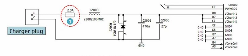
| Protection Location | Company J | Company W | Company S | Prosemi | |
| Usage Point 1 | Mobile Phone Power / Charging Port | F06F Series 0.75A - 3A | 0603WCF Series 0.75A - 3A | S0603-F Series 0.75A - 3A | 0603FA Series 0.75A - 3A |
❷E-Cigarette Power Supply Schematic
In compliance with EU regulations, electronic cigarettes must be equipped with a fuse to provide input overcurrent protection.
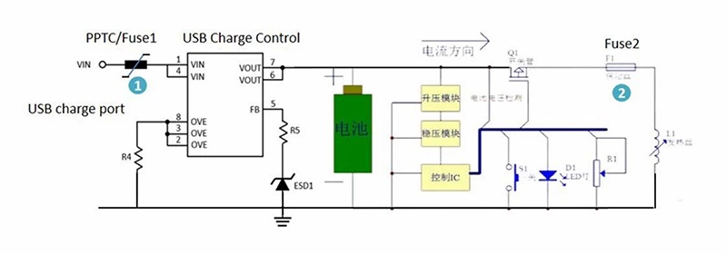
| Protection Location | Company J | Company W | Company S | Prosemi | |
| Usage Point 1 | USB Charging Interface | TLC Series 200mA, 75mA, 100mA | P Series 200mA, 75mA, 100mA | NA | SRF1206P200 SRF0603P075 SRF0603P100/6 |
| Usage Point 2 | Heater Wire Terminal | F06 Series 3A, 1.5A, 1A, 0.75A | 603WCF Series 3A, 1.5A, 1.25A, 1A | S0603-F Series 3.0A, 1.5A, 1A, 0.75A | 0603FA, 3A, 1.5A, 1.25A, 1A, 0.75A |
❸ Laptop Power Distribution Schematic
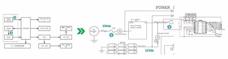
| Protection Location | Company J | Company W | Company S | Prosemi | |
| Usage Point 1 | AC Adapter Input | F12FH Series 1A - 7A TA Series 1A - 7A |
1206WJF Series 1A - 7A WCAF2410F Series 1A - 20A |
S1206-F Series 1A - 7A S6125-F Series 1A - 20A |
1206FA Series 1A - 7A 2410FA Series 1A - 20A |
| Usage Point 2 | Li-ion Battery Charging Terminal | F12T Series 7A 12F Series 8A, 10A, 12A |
1206WJS Series 7A 1206WJF Series 8A, 10A, 12A |
S1206 Series 7A S1206-FA Series 8A, 10A, 12A |
1206TD-7A (Slow Blow) 1206FA-8A (Fast Blow) 1206FA-10A(Fast Blow) 1206FA-12A(Fast Blow) |
❹ Smartwatch Functional Block Diagram
| Protection Location | Company J | Company W | Company S | Prosemi | |
| Usage Point 1 | Wireless Charging Input Terminal of Smartwatch | F06 Series, Fast Blow, 2A | 0603WCF Series 2A | S0603-F Series 2A | 0603FA-2A (Silkscreen Marking “K”) |
| Usage Point 2 | Positive Output Terminal of Rechargeable Lithium Battery Protection Board | F12 Series, Fast Blow, 8A | 1206WJF Series 8A | S1206-F Series 8A | 1206FA-8A (Silkscreen Marking “M”) |
2.Automotive Electronics
❶ Battery Management System (BMS) for Automobiles
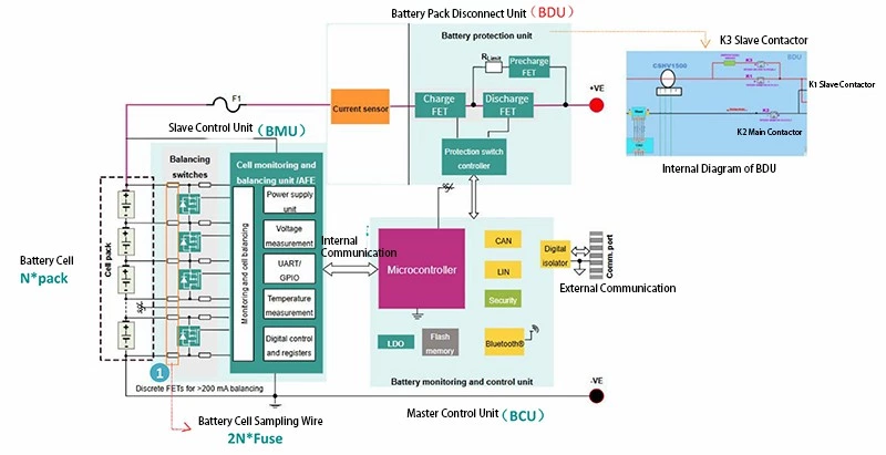
Overcurrent Protection Design and Selection for Automotive BMS
In the battery management system (BMS), a commonly adopted protection scheme for sampling boards in the industry is to connect one fuse in series with each voltage detection line and balancing line. This approach helps prevent short-circuit issues between lines that may be caused by various uncontrollable factors.
When selecting fuses, multiple factors must be carefully considered. These include the influence of temperature on fuse performance, the fuse’s breaking capacity under wiring harness short-circuit conditions, and the impact of the fuse’s DCR (direct current resistance) on the sampling circuit.
From the perspective of specific application scenarios, the sampling current in the detection circuits is relatively small—typically at the milliampere level. Therefore, commonly used fuse specifications include 1206 FA 0.5 A and 0603 FA 1 A. For balancing circuits, which can be either active or passive and exhibit certain variations in current, fuse specifications in the range of 1 A to 5 A are typically selected.
| Protection Location | Company L | Prosemi | |
| Usage Point 1 | Protection of BMU Balancing Circuits | 437 Series 0.5A 438 Series 1A ~ 5A |
1206FA-0.5A 0603FA-1A ~ 5A |
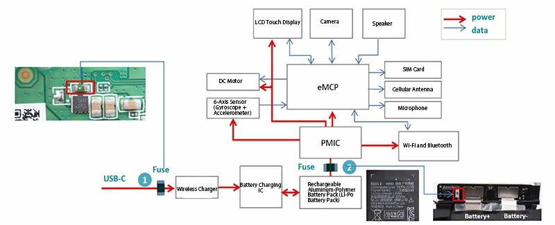
❷ Communication and Entertainment System Block Diagram
| Protection Location | Company L | Prosemi | ||
| Usage Point 1 | Fuse | 12 V Battery | 437A, 440A, 441A | 0603FA, 1206FA |
| Usage Point 2 | PPTC | USB Port | ASMD, miniASMD | / |
| Usage Point 3 | SBD | AUX Port | ||
| Usage Point 4 | Fuse | DC Output Port | 437A, 440A, 441A | 0603FA, 1206FA |
| Usage Point 5 | ESD | Display | AQ3045 | PTN102L05S5B9-T |
| Usage Point 6 | PPTC | Camera | ASMD, miniASMD | / |
| Usage Point 7 | Polymer ESD | Cellular Network (LTE, GSM, etc.) | AXGD | UPEP2D24T0402-T |
| Usage Point 8 | Polymer ESD | GPS Input | AXGD | UPEP2D24T0402-T |
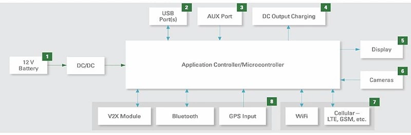
❸Digital Rear-View Camera, Front-Facing Camera, and Lane Departure Detection Camera
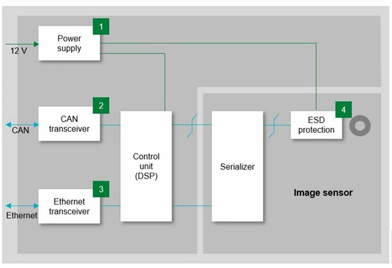
| Protection Location | Company L | Prosemi | ||
| Usage Point 1 | Fuse | 12-Volt Power Supply Input | 437A Series 438A Series 440A Series |
0603FA 1206FA |
| Usage Point 2 | ESD | Controller Area Network (CAN) Transceiver | AQ24COM-02 | PTT233G20S24BA44-T |
| Usage Point 3 | ESD | Ethernet Communication Transceiver | AXGD, AQ3102, AQ3400 | UPEP2D24T0402-T |
| Usage Point 4 | ESD | ESD | AQ3045 | PTN102L05S5B9-T |
❹eCall (Emergency Call System) Block Diagram
Commercial and passenger electric vehicles equipped with eCall automatically notify emergency rescue personnel in the event of a collision.
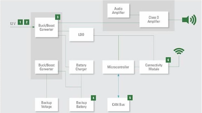
| Protection Location | Company L | Prosemi | ||
| Usage Point 1 | Fuse | 12-Volt Power Supply Input | 437A, 438A, 440A, 501A | 0603FA, 1206FA |
| Usage Point 2 | TVS | 12-Volt Power Supply Input | SLD8S, SZ1SMA, SZSMF4L | SM8S-T, SMAJ-T, P4SMFL-T |
| Usage Point 3 | SBD | DC-DC Boost-Buck Converter | ||
| Usage Point 4 | PPTC / Fuse | Backup Battery | ASMD, miniASMD / 437A, 438A, 440A, 501A | 0603FA, 1206FA |
| Usage Point 5 | ESD | Controller Area Network (CAN) Transceiver | AQ24COM-02 | PTT233G20S24BA44-T |
| Usage Point 6 | Polymer ESD | Connector Module | AXGD | UPEP2D24T0402-T |
❺Electric Vehicle Headlamps, Taillamps, and Turn Signal Indicators
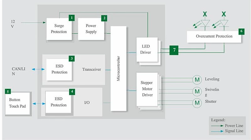
| Protection Location | Company L | Prosemi | ||
| Usage Point 1 | TVS | 12-Volt Battery | SLD | SM8S-T |
| Usage Point 2 | SBD | Power Supply Unit | ||
| Usage Point 3 | ESD | CAN Bus ESD Protection | AQ24COM-01 AQ24COM-02 |
|
| Usage Point 4 | ESD | Touch Key ESD Protection | AQ1005 | |
| Usage Point 5 | High I2T Fuse | Overcurrent Protection | 501A | 1206FA High I2T |
| Usage Point 6 | PLED | LED Driver | PLEDxUx-A PLEDxS-A |
PLEDXXBS-T PLEDXXAFS-T |
❻Radar (provides data for electric vehicle collision avoidance, automatic braking, and autonomous driving systems)
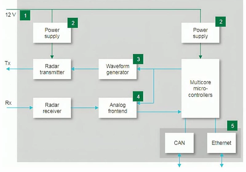
| Protection Location | Company L | Prosemi | ||
| Usage Point 1 | Fuse | 12V | 437A, 440A, 441A, 501A, 881 | 0603FA, 1206FA |
| Usage Point 2 | TVS | Power Supply Unit | SZ1SMB, SLD8S, SZSMF4L | SM8S-T, SMBJ-T, P4SMFL-T |
| Usage Point 3 | ESD | Waveform Generator | AQ3045 | PTN102L05S5B9-T |
| Usage Point 4 | Polymer ESD | Analog Front End (AFE) | AXGD | UPEP2D24T0402-T |
| Usage Point 5 | ESD / Polymer ESD | Ethernet | AQ24CANA, AO24CANFD, AQ24COM-02, AQ3102, AXGD | PTT233G20S24BA44-T, UPEP2D24T0402-T |
❼Vehicle-to-Vehicle (V2V) Communication (enables collision avoidance and supports
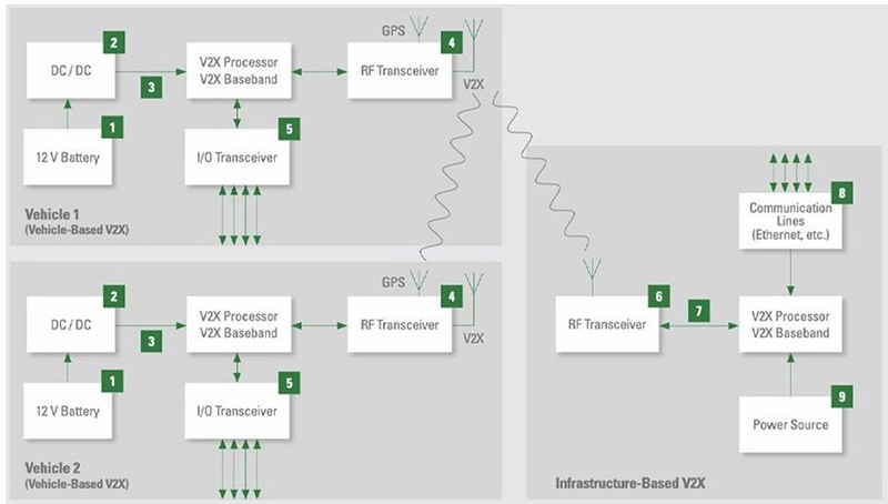
| Protection Location | Company L | Prosemi | ||
| Usage Point 1 | Fuse | 12-Volt Battery | 437A, 438A, 440A | 0603FA, 1206FA |
| Usage Point 2 | TVS | DC / DC | SZ1SMB, SLD8S | SM8S-T, SMBJ-T |
| Usage Point 3 | ESD | V2X Processor and V2X Baseband | SZ1SMA, SZ1SMB | SMAJ-T, SMBJ-T |
| ,Usage Point 4 | Polymer ESD | RF Transceiver | AXGD | UPEP2D24T0402-T |
| Usage Point 5 | Polymer ESD | RF Transceiver | AXGD | UPEP2D24T0402-T |
| Usage Point 6 | Fuse | V2X Processor and V2X Baseband | 437A, 438A, 440A | 0603FA, 1206FA |
| Usage Point 7 | TVS | Power Supply | SZ1SMA, SZ1SMB | SMAJ-T, SMBJ-T |
㈢Medical Electronics
❶Blood Pressure Monitor
The electronic blood pressure monitor operates as follows: the device contains a built-in air pump, which pressurizes the cuff. The resulting pulse and blood pressure signals are detected by a pressure sensor and transmitted to the embedded System-on-Chip (SoC). After processing by the SoC, the device not only displays blood pressure and related data on the device screen but can also deliver results via voice announcement.
Regarding power supply, the electronic blood pressure monitor generally supports two modes: AC adapter power and USB Type-C input. To provide overcurrent protection, a blue fuse is soldered at the power input. The fuse has a 0603 package, is of fast-blow type, rated at 1.5 A, marked with the surface silkscreen “H”, and it is recommended to use the model 0603FA-1.5A.
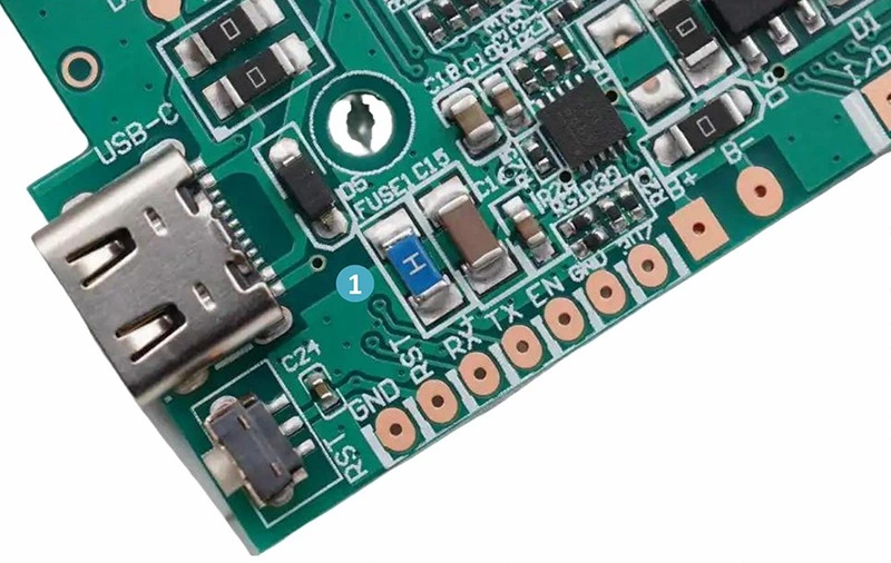
| Protection Location | Company L | Company W | Company S | Prosemi | |
| Usage Point 1 | USB Type-C Input Port | F06F Series 1.5A | 0603WCF Series 1.5A | S0603-F Series 1.5A | 0603FA-1.5A (Silkscreen Marking “H”) |
❷Blood Glucose Meter
The portable electronic blood glucose meter is powered by a 3 V supply, typically provided in one of two ways: either by two AAA batteries or by a single 3 V CR2032 lithium battery. The device’s normal operating current is 20 mA, with a peak current of up to 40 mA. To provide overcurrent protection, a fuse is usually installed at the power input. The fuse has a 0603 package, is of fast-blow type, rated at 0.5 A, and is marked with the surface silkscreen “F”.
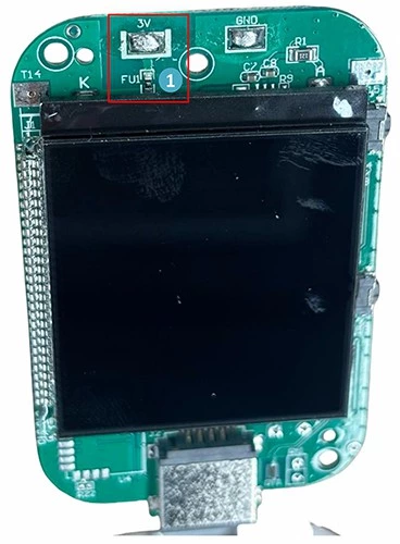
| Protection Location | Company S | Prosemi | |
| Usage Point 1 | Power Input Terminal | S0603-F Series 0.5A | 0603FA-R500 (Silkscreen Marking “F”) |
❸Pulse Oximeter
The pulse oximeter operates based on the differential light absorption characteristics of oxyhemoglobin and deoxyhemoglobin: oxyhemoglobin absorbs more near-infrared light while allowing more red light to pass through, whereas deoxyhemoglobin primarily absorbs red light and allows more near-infrared light to pass.
Based on this principle, each pulse oximeter contains a sensor probe with two light-emitting diodes (LEDs)—one emitting red light and the other emitting near-infrared light—and a photodetector positioned opposite the LEDs. The photodetector measures the transmitted light intensity at both wavelengths. Using a specific algorithm, the device processes the differences in intensity readings between the two wavelengths to calculate the blood oxygen saturation (SpO₂).
Additionally, to ensure the safety of the device and downstream circuits, the pulse oximeter’s USB interface includes an overvoltage and overcurrent protection circuit, which effectively prevents spikes generated during plug-in events from impacting the downstream circuitry.
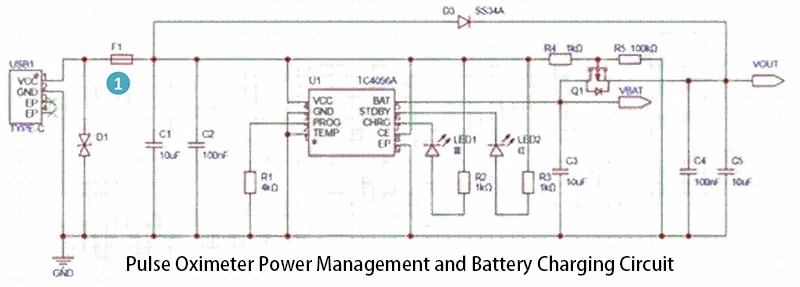
| Protection Location | Company J | Company W | Company S | Prosemi | |
| Usage Point 1 | USB Type-C Input Port | F06F Series 1.5A | 0603WCF Series 1.5A | S0603-F Series 1.5A | 0603FA-1.5A |
Conclusion
This concludes the introduction to our ultra-low DCR, ultra-thin film fuse products. We sincerely thank you for your trust and interest in the Prosemi brand. Your recognition is the core motivation behind our continuous efforts to enhance product performance and optimize service experience. We remain committed to a customer-centric approach, striving to provide reliable support for your application needs through high-quality products.
If, after reviewing our products, you wish to obtain detailed datasheets, accurate pricing information, or request free samples to verify product compatibility, you are welcome to contact us directly (nancy.chen@prosemitech.com). Alternatively, you may access the required information through our official website: www.prosemicsr.com/smd-fuse.
We are dedicated to providing efficient, professional support to ensure the smooth progress of your projects, and we look forward to further communication to help address practical challenges in your applications.